Introduction
Check the following points upon receipt of your pump:
(1) Is the pump exactly what you ordered? Check the name plate. It is especially important that you check whether the pump is to be used with 50 Hz or 60 Hz.
(2) Has any damage occurred during shipment? Are any bolts or nuts loose?
(3) Have all necessary accessories been supplied? (For a list of standard accessories See Construction.)
We recommend that you keep a spare pump on hand in case of emergencies. Keep this instruction manual in a safe place for future reference.
Check the following before beginning installation.
Insulation resistance measurement:
For three phase motor:
With the motor and cable (excluding the power supply connections) immersed in water, use a megger to measure the insulation resistance between the ground wire and each phase of the motor, and again between each phase of the motor.
For single phase motor:
Use a megger to measure the insulation resistance be tween both prongs of the plug and grounding wire.
The megger should indicate an insulation resistance of not less than 20 mega ohms. While making the measurement, keep the power supply cable off the ground.
Installation
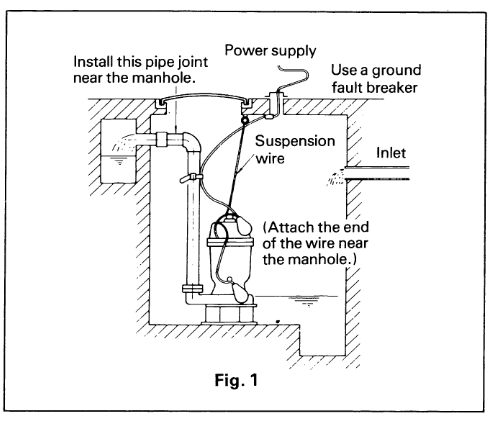
(1) Under no circumstances’ should the cable be pulled while the pump is being transported or installed. Attach a chain or rope to the grip and install the pump.
(2) This pump must not be installed on its side or opera ted in a dry condition. Ensure that it is installed upright on a secure base.
(3) Install the pump at a location in the tank where there is the least turbulence.
(4) If there is a flow of liquid inside the tank, support the piping where appropriate.
(5) Install piping so that air will not be entrapped. If piping must be installed in such a way that air pockets are unavoidable, install an air release valve
wherever such air pockets are most likely to develop.
(6) Do not permit end of discharge piping to be sub merged, as backflow will result when the pump is shut down.
(7) Non-automatic pumps (model DVS) do not have an automatic operating system based on built-in floats.
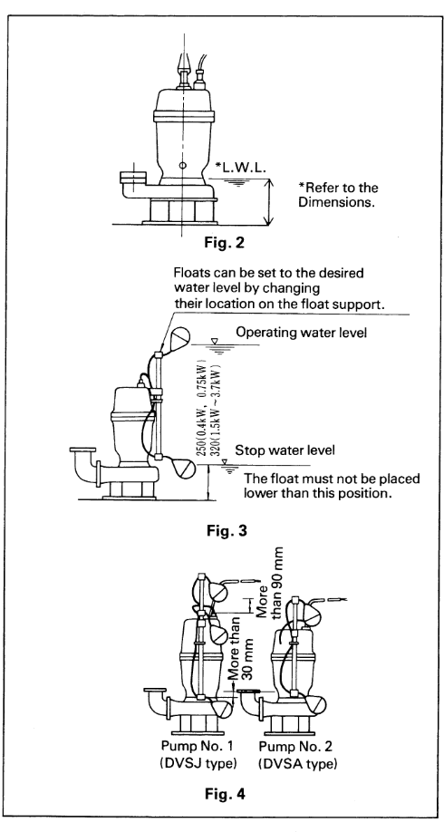
Always keep an eye on pump operating water level. Do not operate the pump for a long time with the water level near the minimum operating level as the automatic cut -off switch incorporated inside the motor will be activated. To avoid dry operation, install an automatic operating system, as shown in Fig. 2 and maintain a safe operating water level.
(8) For automatic pumps (DVSA), install the floats as shown in Fig. 3. The pump may not start if a float switch touches the wall of the water tank or the
piping. Install the floats so that this will not happen.
(9) Models DVSJ pue DVSA will undergo automatic alternate operation when they are paired. Position the floats for these automatic alternate operation pumps as shown in Fig. 4. The pumps may not operate correctly if the floats are in the wrong location.
Refer to the quick discharge connector instruction manual for details on the installation of pumps so equipped.
Electrical wiring
(1) Wiring
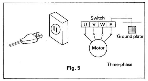
a) Wire as indicated for the appropriate start system as shown in Fig. 5.
b) Loose connections will stop the pump. Make sure all electrical connections are secure.
(2) Cable
a) Never let the end of the cable contact water.
b) If the cable is extended, do not immerse the splice in water.
c) Fasten the cable to the discharge piping with tape or vinyl strips.
d) Install the cable so that it will not overheat. Overheating is caused by coiling the cable and exposing it to direct sunlight.
(3) Grounding: Pleaseground motor for safety.
(4) Use short circuit breakers to prevent danger of electrical shock.
Operation
- Before starting the pump
(1) After completing installation, measure the insulation resistance again as described in Installation.
(2) Check water level.
If the pump is operated continuously for an extended period of time in a dry condition or at the lowest water level, the motor protector (less than 7.5kW) or the thermal detector (more than 11kW) will be activated.
Constant repetition of this action will shorten pump service life. Do not start the pump again in such a situation until after the motor has completely cooled. - Test operation ….
Non-automatic pump (DVS)
Automatic pump (DVSA)
(1) Turn the operating switch on and off a couple of times to check for normal pump start.
For the DVSA pump, the upper float switch must be raised for the pump to start.
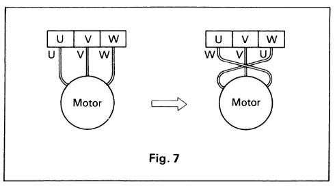
(2) Next, check direction of rotation. If discharge volume is low or unusual sounds are heard when the pump is operating, rotation has been reversed. When this happens, reverse two of the three wires (see Fig. 7). - Test operation ….
Automatic alternate pumps (DVSJ)
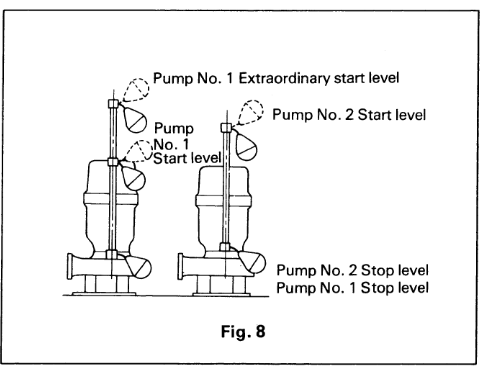
Check automatic alternate operation of pump No.1 (DVSJ) and pump No.2 (DVSA) as follows (see Fig. 8).
(1) When the water level reaches pump No.1 start level, pump No. 1 will start and water will be pumped until pump No.1 stop water level is reached.
At this point the automatic alternate operation circuit built into pump No.1 will stop the pump.
The water level will now be at pump No.2 start level.
Pump No.2 will start and pump water until its stop water level is reached. The process is repeated when the water level is again at pump No.1 start level.
(2) If the water flowing into the water tank exceeds the amount being pumped by pump No. 2 (abnormal water increase) and the water level rises to pump No.1 abnormal start water level, pump No. 1 will start to
operate. The two pumps will then be operating simultaneously in parallel operation.
Maintenance
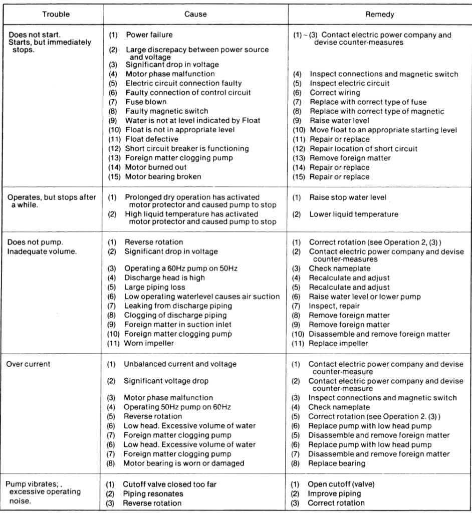
Check pressure, output, voltage, current and other specifications. Unusual readings may indicate trouble. Refer to Troubleshooting and correct as soon as possible.
- Daily inspections
(1) Check current and ammeter fluctuation daily. If am meter fluctuation is great, even though within thelimits of pump rating, foreign matter may be clogging the pump.
If the quantity of liquid discharged falls suddenly, foreign matter may be blocking the suction inlet. - Regular inspections
(1) Monthly inspections
Measure the insulation resistance. The value should be more than 1M ohm. If resistance starts to fall rapidly even with an initial indication of over 1M ohm, this may be an indication of trouble and repair work is
required.
(2) Annual inspections
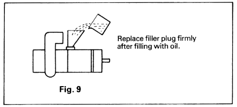
The service life of the mechanical seal can be prolonged by replacing the oil in the mechanical seal chamber once a year. Water mixed with the oil or a cloudy texture are indications of a defective me chanical seal requiring replacement. When replacing the oil, lay the pump on its side with filler plug on top as shown in Fig. 9.
Inject turbine oil No. 32 (ISO VG-32) until it overflows.
(3) Inspections at 3-5 year intervals
Conduct an overhaul of the pump. These intervals will preclude the possibility of future trouble.
- Precautions when operation is suspended
(1) If operation is to be suspended for a prolonged period of time with the pump immersed in water, measure the insulation resistance of the motor occasionally. If resistance is normal, operate pump to prevent rust from developing on moving parts. Follow the instructions under Operation when pump operationn is to be resumed.
(2) For dry storage, clean out pump and store in a dry place. Follow the instructions under Installation and Operation when pump operation is to be resumed. - Note: For cold weather storage, turn the unit on its side, discharge elbow in the down position. This is to make sure all water has drained from the volute. Then store the unit in a dry place.
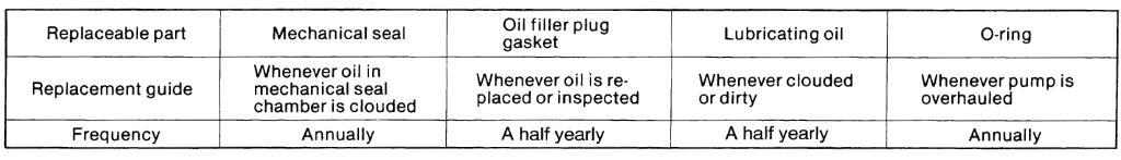
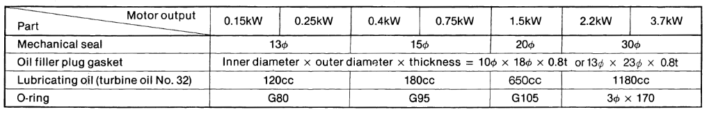
Parts that will need to be replaced
Replace the appropriate part when the following conditions are apparent.
Troubleshooting
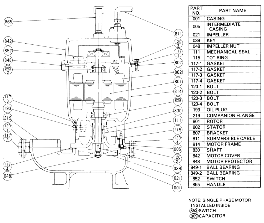
Construction
Sectional view
This drawing represents one of the standard models.
There may be some variations according to models.
Disassembly
When disassembling pump, provide a piece of cardboard or plywood to place the different parts on as you work.
Do not pile parts on top of each other. They should be laid out neatly in rows. As the “0” ring and gasket can not be used again once they are removed, have replacement parts ready.
Disassemble in the following order, referring to the sectional view.
Be sure to cut off power source before beginning disassembly.
The procedure for disassembling is given as follows.
(1) Loosen nuts and remove casing bolts (120-4).
Raisethe motor section and remove pump casing.
(2) Remove impeller nut (048) and impeller.
(3) Remove oil plug (193) and drain lubricating oil.
(4) Remove intermediate casing bolts (120-2) and inter mediate casing carefully.
(Remember that any lubricating oil remaining in the mechanical seal chamber will flow out.)
(5) Carefully remove mechanical seal, taking care not to scratch sliding surface or motor shaft.
Assembly
Reassemble in reverse order of disassembly.
Be careful of the following points.
(1) Replace “0” rings and gaskets.
(2) Replace every worn or damaged part.
(3) Check condition of ball bearings, replace, if necessary or if they fail to retain grease.
(4) Secure the bolts slowly and symmetrically so as to prevent one-sided tightening.
(5) After completion of assembly, ensure pump can be turned smoothly by hand.
Note 1: During re-assembly, rotate the impeller by hand and check for smooth rotation after impeller is replaced (step 2). If rotation is not smooth, perform steps 5) through 3) again.
Note 2: Upon completion of re-assembly step 1) rotate the impeller by hand from the suction inlet and check that it rotates smoothly without touching the suction cover before operating the pump.
Leave a Reply