Model CSA & CNA
Safety Information and Introduction
WARNING
Before handling this pump, always disconnect the power first. No open flame or use spark able electrical devices or flames in a septic (gaseous) or possible septic sump.
Do not work under heavy Suspended object unless there is a positive support under it to stop its fall in event of sling or, hoist failure. Disregard of this warning could result in personal injury.
This pump should only be serviced by a qualified person or a factory trained person
CAUTION
This instruction manual includes necessary items for installation, operation and maintenance.
Read this manual carefully to ensure correct installation, operation and maintenance.
Be sure to keep this instruction manual on hand for future reference.
Be careful not to exceed the given specifications in the use of your products.
Introduction
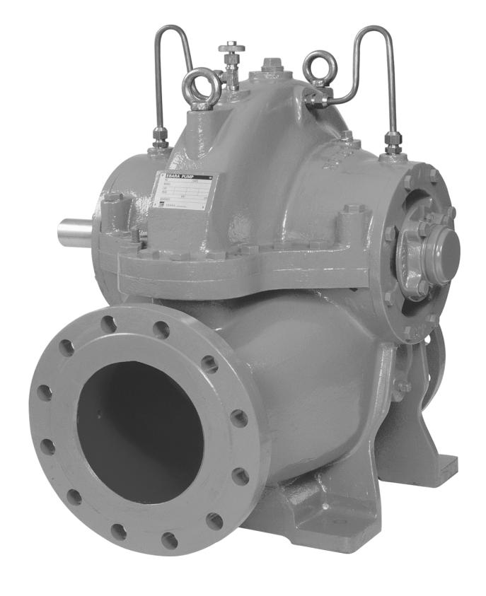
Thanks you for purchase of this EBARA Model CSA/CNA Horizontal Split Casing Pump.
EBARA has manufactured this pump with due care so that it can be operated with case.
However, if it is not property operated, unexpected accident may result.
Accordingly, you are requested to operate this pump according to this instruction manual and to keep this manual for reference.
Installation
If the pump is installed properl y and maintained with
due care, it can be operated quietly and safel y for long
time. Install the pump and connect piping wi th
reference to following items:
1.Unpacking
Upon arrival of the pump at site, check the following:
(1) Check that the pump is as ordered by referring to the name plate.
(2) Check for possible shipping damage and loosed nuts or bolts.
(3) Check for missing accessories. If defects are found, contact your nearest service representative, referencing the items listed on nameplate.
(4) Handle carefully without damage to the units as bellows:
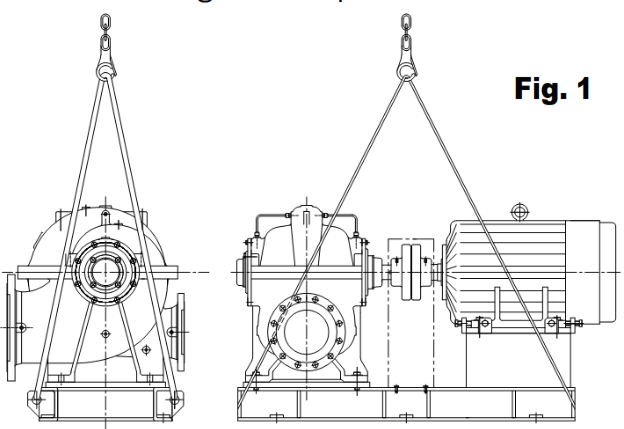
- To lift the pump, suspend with cable as shown In Fig. 1, so that loading in even. Please do not use excessive large size cable.
- Handle with care so that piping, valves, Instrument, etc, are not broken.
- Lifting hook bolts attached to upper casing are used for their removal only. They must not be used for lifting the entire pump unit.
(5) If storage is required after unpacking, place the pump indoors without fail.
Before pump shipment, the coupling, flanges, shaft, and other external machined pump surface have usually been coated with rust preventative oil (NOX-RUST 366).
Internal components have also been coated with rust preventative oil (RUST-VET377).
When the pump is stored for extended periods, hermetically seal all openings after inserting, dry agent (silica gel) or rust-proof agent (Dyana). Use thinner to remove the internal coating before operation.
2. Installation Site
(1) Select a pump site, easy for maintenance and inspection.
(2) Provide a suitable barrier to prevent entry of an authorized persons around pump.
(3) Install the pump as close to the water supply as possible. As high suction head may cause vibration, noise and pump failure, the suction head should be re-checked. Since the suction head should be reduced if liquid temperature is high, install the pump in reference to Re NSPH (Required Net Positive Suction Head) so that average net positive suction head (Av NPSH) is larger than the Required NPSH.
3. Cautions on Piping
(1) As suction discharge pipe load applied to the pump causes eccentricity, both pipes should be provided with adequate support.
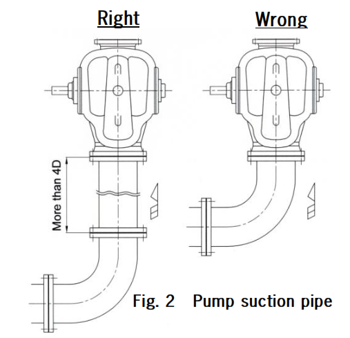
(2) Minimum number of suction elbows with bend radius as large as possible may be installed at some distance from pump inlet (Fig. 2)
(3) Install a check valve for reverse flow prevention when the discharge pipe is too long, actual head is high, water is fed pressure tank, or when two or more pumps are operated in parallel. Install the check valve between the pump and the sluice valve.
(4) If there is danger of water hammer, a quick closing check valve should be installed on the discharge side.
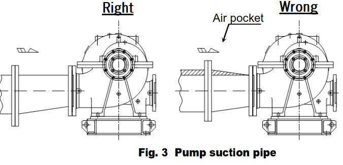
(5) If a pipe of different diameter than pump flange is used, an eccentric type reducer should be installed so as not produce any air pocket. (Fig. 3)
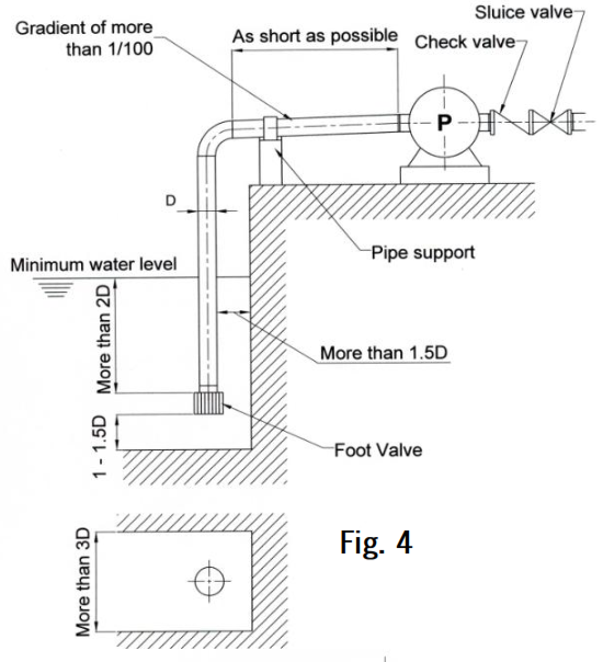
Suction pipe for positive suction
(1) Install a foot valve at the end of suction pipe and connect the pipe as shown in Fig. 4. The foot valve must be ordered separately.
(2) Connect horizontal portion of pipe with a gradient of more than 1/100 toward pump, as shown in Fig.4.
(3) Ensure that flange does not permit air intake.
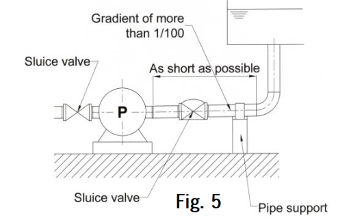
Suction pipe for influx or force feed
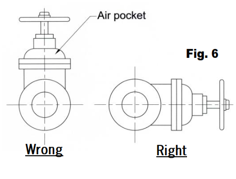
(1) Install a sluice valve on suction pipe between the pump and tank as shown in Fig. 5. Sluice valve should be installed with their handles
facing sideways so as not to produce any air pocket Fig. 6.
(2) Connect horizontal portion of pipe with a gradient of more than 1/100 toward pump, as shown in Fig. 5.
4.Installation
The pump has been aligned with driver before shipment. However, adjustment for alignment is necessary at the site.
Install and center according to the following procedure:
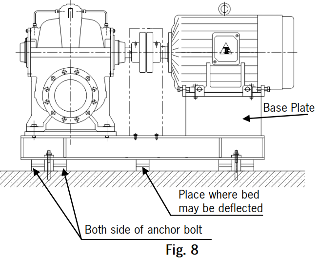
(1) After chipping the foundation, arrange one parallel liner and two taper liners on both side of the anchor bolt hole of the base as shown in Fig. 7.
(2) Place the pump plus common bed on these liners and install the anchor bolt in the anchor bolt hole.
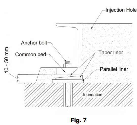
(3) Determine the position and height of the pump level by using the casing machined surface, to obtain a horizontally of 0.1 mm/m as the reference value. The pump height can be easily adjusted with taper liners.
(4) After installing anchor bolt, pour mortar into the anchor bolts holes and allow to be harden Mortar will harden in about 4 days, although this
period more or less differs according to the open air temperature, humidity and the compound ratio.
(5) After the mortar has hardened, arrange the liners used in paragraph (1) as close to and on either side of the anchor bolt. If the distance between anchor bolts exceeds 1m, install additional liners between these anchor bolts.
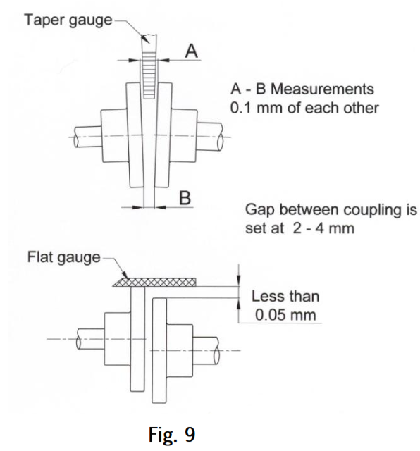
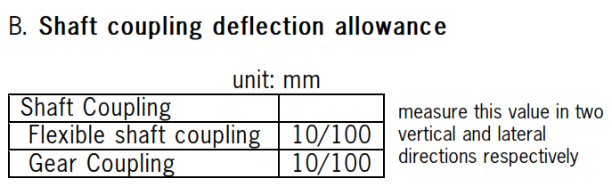
(6) First Centering
Perform centering while adjusting the taper liners. Axial center offset and surface deflection of coupling must be within the allowance shown in Fig. 9, while using a flat gauge, taper gauge, thickness gauge or dial gauge as shown in Fig. 9. Measure these values with anchor tightened. Be careful since these values very considerably according to whether anchor bolts
are tight or loose. Install the driver on the base by placing several liners, so that driver is mostly 1 to 2 mm higher than base surface.
(7) After completion of centering, securely tighten anchor bolts and pour mortar around the pump. Pour mortar into the space of the bed seat.
(8) After mortar has been harden, tighten anchor bolts securely again and connect pump suction and discharge piping. If shaft coupling offset
exceeds 0.2 mm as a result of pipe connections, disconnect pipe connection and adjust pipe support. Repeat this adjustment until piping is correct.
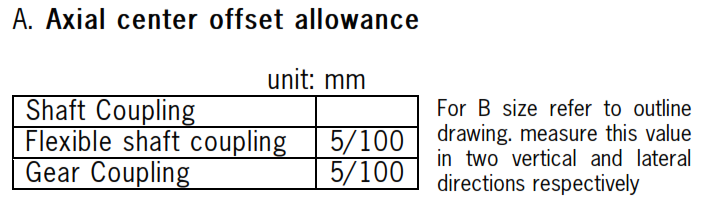
(9) Second centering
After piping has been completed correctly, set the axial center offset of the shaft coupling of the pump and driver to less than the value shown in Fig. 8. Adjust this value by exchanging shims between the driver and common bed as required.
5.Electrical Wiring
WARNING
Check that the power is locked off and disconnected before working on pump.
All electric work should be performed by a qualified electrician and all national and local electrical codes must be observed
CAUTION
Measure the insulation resistance. The value should be more than 1 mega ohm. While making The measurement, keep the power supply cable off the ground.
Before installation check rotation. The standard rotation is clockwise when viewed from motor side. Read ELECTRICAL WIRING.
Power supply equipment and wiring for the motor must be in accordance with the instruction manual for the motor, electrical equipment technical standard and existing regulation. Incomplete wiring and grounding by an unqualified persons is against the law and very dangerous.
In order to prevent electric shocks, install a short circuit breaker according to local regulations. This breaker must be supplied by costumer. A motor protective device, to prevent damage to the motor due to overload, etc., should be installed.
Operation
CAUTION Check rotation. Pump should be started with gate valve closed, than the operator should open the valve gradually.
1. Cautions Before Starting Operation
(1) Turn the pump by hand and check for smooth rotation. If pump rotation is difficult or uneven, it may be caused by internal rust etc. Locate cause and eliminate.
(2) Operate the driver only by inching operation so as to confirm direction of rotation. Then, connect the shaft coupling and install shaft coupling guard.
(3) Prime the pump. Never operate the pump without prime. Open the air vent plug or valve mounted on the pump discharge side.
So as to exhaust air or other gas completely and confirm the pump is fully
primed. Turn the pump shaft manually to discharge air and gas.
(4) After priming has been completed, close the discharge valve.
2. Start Operation and Stop
(1) Ensure that suction valve is fully open and the discharge valve is fully closed.
(2) Turn the start switch off and on once or twice to ensure the pump is operating normally. If there are no malfunctions, the pump may be placed in continuous operation since pump shut -off operation causes rapid liquid temperature rise inside pump, with resultant damage, shut-off operation should be confined to short periods.
(3) Check each part of the pump and driver for current voltage, lubrication of each part, rotation noise, vibration, discharge and suction pressure, etc. If there is a possibility that foreign substances may be introduced into the pump, during the initial stage of operation, provide a temporary strainer on the suction side just before the pump. Provide a pressure gauge between the strainer and the pump to monitor pressure drop due to strainer.
Increased pressure drop indicate strainer clog, so pump must be stopped and
strainer cleaned. If suction pressure becomes low due to excessive pressure
drop there is danger of pump burn-out.
Do not remove strainer until all foreign substance are completely removed from the system and piping.
(4) Re-check pump and driver 30 to 60 minutes after start.
(5) During stop operation, gradually close the discharge valve before turning off the prime mover.
3.Shut-down and Emergency Shut-down
(1) When the pump stops due to power failure, turn of the switch and closed
discharge valve. (This prevents sudden start of pump when power is restored).
(2) Power emergency shut-down, switch off electric power and close discharge valve.
4. Standby Pump
For standby pump operation, fully open the suction and discharge valve. Fill the pump with the liquid so that suction pressure is applied. Stop reverse pressure with check valve only and start the pump is when restarting.
Maintenance
CAUTION
Disconnect power cable from power source before servicing unit.
Normal maintenance should be done by qualified personnel.
In order to maintain best operating conditions for the pump the following maintenance and checks should be provided, pressure gauge and compound gauge cocks should be closed except when taking readings. This will prevent instrument damage.
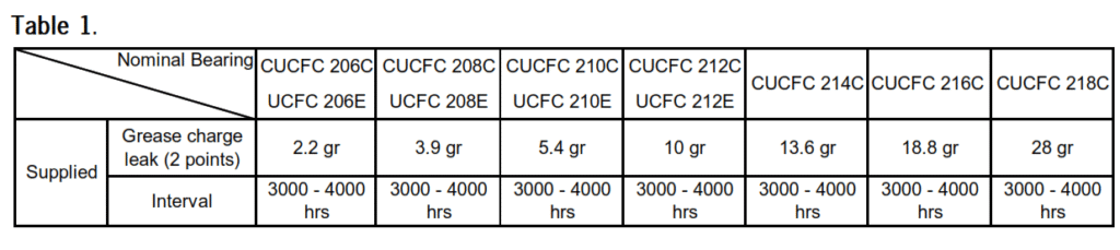
(1) Supply and replacement of bearing lubricant. To supply grease, fill from the upper nipple with the amount and at the intervals shown in table 1. Excessive grease will cause overheat. Applicable grease should be mineral oil and metallic soap base.
(2) Temperature on the bearing casing should not exceed room temperature plus 40°C or 80°C. If this temperature is exceeded, stop operation immediately and check.
(3) Do not start the pump frequently otherwise the pump may be damage. Suppress the starting frequency as follows:
| Motor output | Starting frequency |
| Lower than 7. 5 kW | Less than 6 times per hour |
| 11 Kw – 22 kW | Less than 4 times per hour |
| Higher than 22 kW | Less than 3times per hour |
(4) Pressure, current, vibration, noises etc. which differ greatly from normal values are a symptom of trouble. Take counter measure immediately. For this purposed, it is recommended that records be kept.
Check the following items:
Suction and discharge pressures
Current value and deviation
Bearing temperature (max. 80° C on bearing casing)
Vibration (on bearings and pump casing)
Noises
(5) Turn off the switch without fail before checking pump.
(6) Turn the pump shaft by hand once every week if the pump is stopped for long time.
(7) To prevent freeze and subsequent damage to pump during cold weather operation, drain pump or provide insulation.
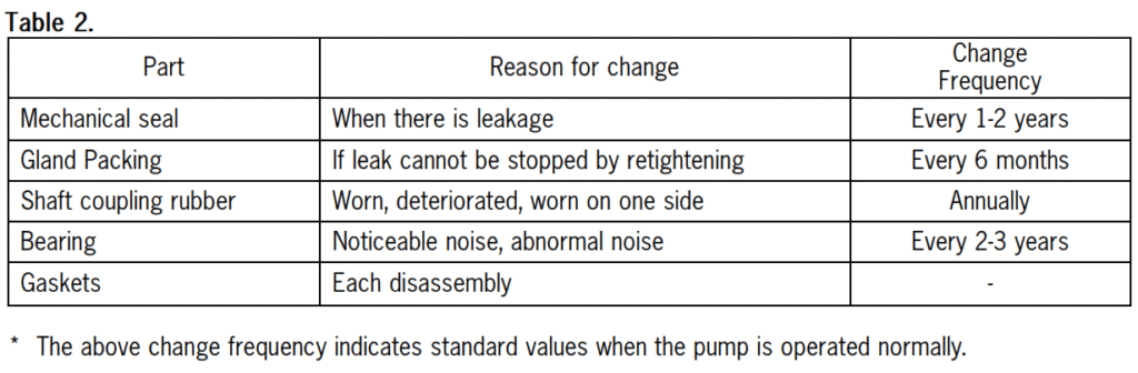
(8) Consumable parts.
Replace parts under the following conditions as shown in table 2.
Disassembly and Assembly
1. Description of Structure
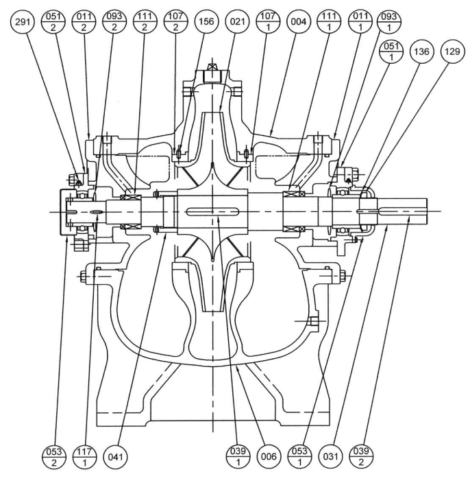
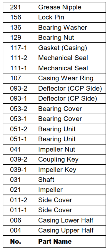
2. Disassembly
Prior to disassembly prepare cardboard or plywood sheet upon which to place disassembled parts. Avoid piling parts on top of each other. Since casing gaskets and side cover gaskets cannot be reused after disassembly, prepare replacements in advance.
Observe the following procedure for disassembly. Before disassembly it is
necessary to turn off all power, close discharge and suction valves, (close valves in minimum flow piping) and open casing drains to completely drain pump.
(1) Remove all auxiliary piping around pump.
(2) Remove coupling connections
(3) Remove bolts of side cover
(4) Remove bolts holding upper and lower casing (two of them are reamer bolts).
(5) Lift off upper casing
(6) Remove bolts for bearing housing
(7) Remove as a unit such rotating component as impeller and liner ring
(8) Place shaft on wooden support and remove shaft coupling, bearing and side cover.
(9) Remove mechanical seal
(10) Remove impeller nut and impeller
Disassembly is now complete.
3. Check
(1) Check liner ring for contact, galling and water.
(2) Check for bent shaft (if liner ring contacts).
(3) Replace bearing if they show excessive wear.
(4) Check impeller for corrosion, wear and cracks.
(5) Replace shaft sleeves and gland packing if scratched or worn. It is recommended that bearing and oil seals be replacedonce every year or so.
4. Assembly
(1) Assembly is in the reverse order of disassembly. Clean all parts with solvent and assemble after through checks for corrosion or scratches.
(2) During assembly replace all used gaskets.
(3) Securely tighten impeller nut set screw bolts and bearing nut.
(4) At mechanical seal assembly, special tool which provided by maker, should be used.
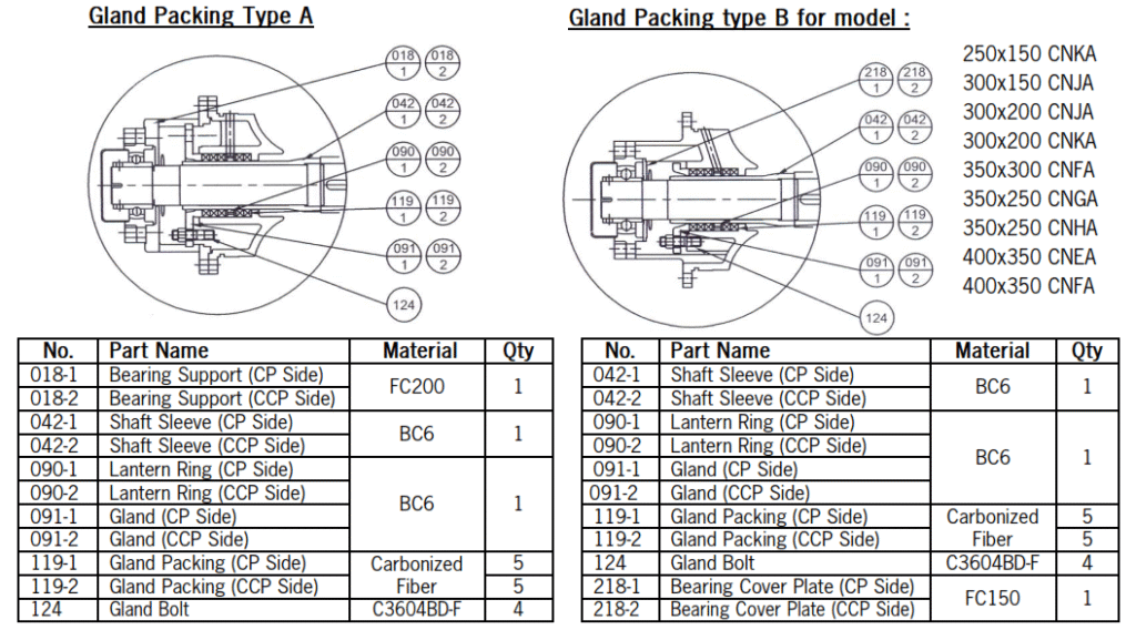
Gland Packings
If leak water increases and cannot be adjusted by tightening gland packings, replace gland packings. If these packings are not properly mounted, water leak will not stop and the sleeve may be worn on one side.
Be careful with the following items. For packing material, refer to sectional view.
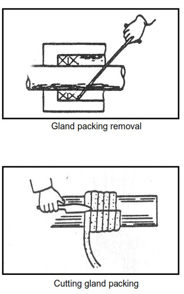
(1) Gland packing removal Remove gland packing with due care by using
the packing tool so as not to damage sleeve of shaft.
(2) Cutting non-molded type gland packing Tightly wind the packing on a round rod or pipe having the same diameter as the shaft, align and cut.
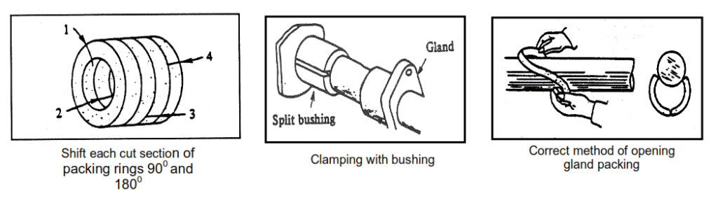
(3) Gland packing installation
(a) Apply a suitable lubricant to the gland packings before mounting and open cut sections with a twisting motion.
(b) Shift each cut section of packing rings 90°C and 180°C . Prepare two split bushing (wooden) or a short two split metallic bushing, place over the packing and push packing into the gland until seated.
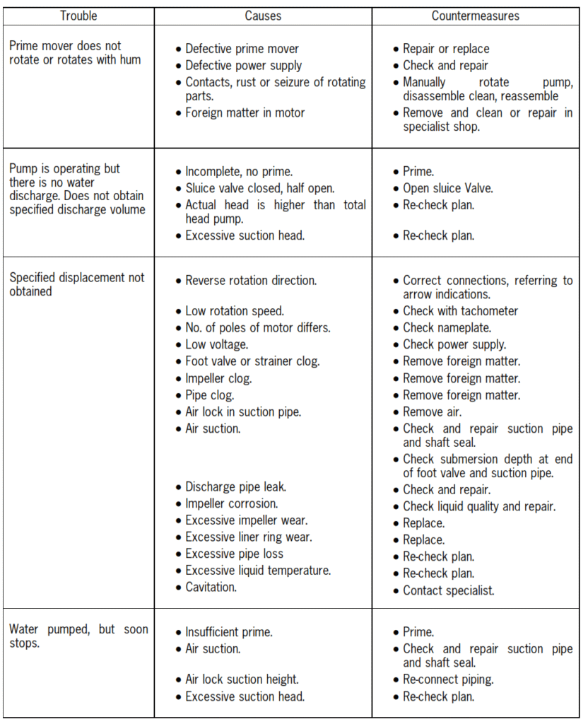
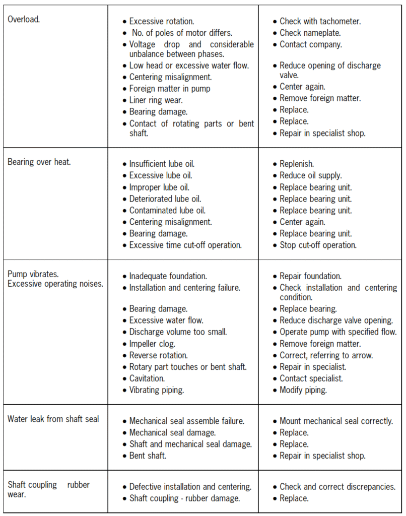
Troubleshooting
Leave a Reply