Installation
1. Location
(1) This pump should be installed indoors (except for option pump of outdoor + motor of outdoor).
(2) There should be ample space around the pump, and securing a large working space for maintenance and inspection.
(3) Provide an enclosure around the pump, or take some other effective measures to prevent unauthorized personnel from coming near it.
(4) Install the pump in a location where it is near a water source, suction height (the height from the suction surface to the center of the pump) is low, and the length of the suction piping is short.
(5) Suction pipe should be as short as possible (check the suction total head at data sheet). In certain cases, such as with hot water, suction head must be lower. To minimize suction pipe loss, excessive use of elbows and valves should be avoided.
(6) Select an airy location with little dust and moisture. Ambient temperature should not exceed 40℃.
(7) Since water leaks can occur from the mechanical seals and gaskets in the pump, take precautions to prevent water from leaking onto the floor or lower levels.
Note
After installation, have unneeded packaging disposed of by a specialist
disposal company.
2. Piping
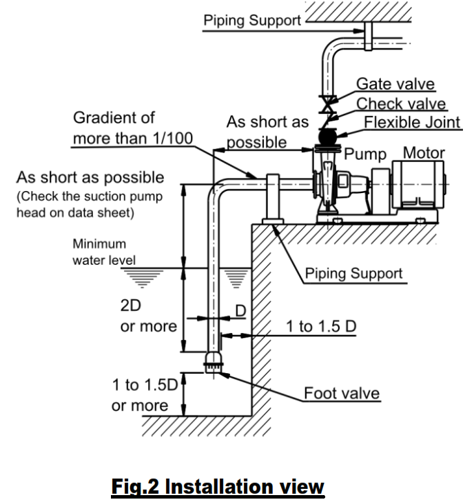
(1) The pump should be installed to piping by Fig. 2.
(2) Install the piping so that the pump casing is not affected by the suction or/and discharge piping.
(3) In the following circumstances, a check valve must be installed:
- a) if the pipes are long,
- b) if the actual pump head is high,
- c) if the pump is to be used in automatic operation,
- d) when water is supplied to the pressure tank, and
- e) if two or more pumps are used in parallel. The check valve should be installed between the pump and the discharge side gate valve.
(4) If the accumulation of air in the top of the pump is unavoidable, provide air vent valves in the trouble areas. However, do not install air vent valves in locations such as suction piping where there is negative pressure, or else air will be sucked.
(5) Do not install the pump in the convex areas of the piping.
(During operation, air or hot water inside the piping in the pump allows steam to build up and cause dry operation.)
(6) If thermal insulation is added to the piping, do not apply it to the motor. Also, if it is installed near the boiler, prevent the heat from the boiler to the pump.
(7) When piping for hot water circulation is used in closed cycle, install an expansion tank or safety valve on the piping.
(8) If there is a possibility of water hammer occurring, install a quick close check valve, and so on.
(9) For negative suction application:
(a) Make the end of the suction piping is 2 times deeper than the diameter of the piping and 1 to 1.5 times apart from the bottom.
(b) Install a foot valve with a strainer on the end of the suction piping to prevent foreign matter from being sucked in.
(c) Install the suction piping so that there is an upward gradient toward the pump of at least 1/100 to prevent air from becoming trapped inside. Also, install joints carefully to prevent air from being sucked in.
(d) Make the suction piping as short as possible, with as few bents as possible, and do not install a gate valve.
(10) For flooding or positive suction application:
Install a gate valve on the suction piping to make disassembly and inspection convenient.
3.Centering
Though the pump and driver have been centered in the factory, the common bed may be distorted when the foundation bolts are inserted during installation. Adjust by placing tapered liners under earth the bed, and center so that the shaft coupling is within the range indicated in Fig.3.
To center a pump which has been purchased without a driver and which is to be directly driven, insert liners under the driver, and center so that the shaft coupling is within the range indicated in Fig.3.
The coupling guard must be removed to make centering adjustments. Be sure to replace before beginning operation.
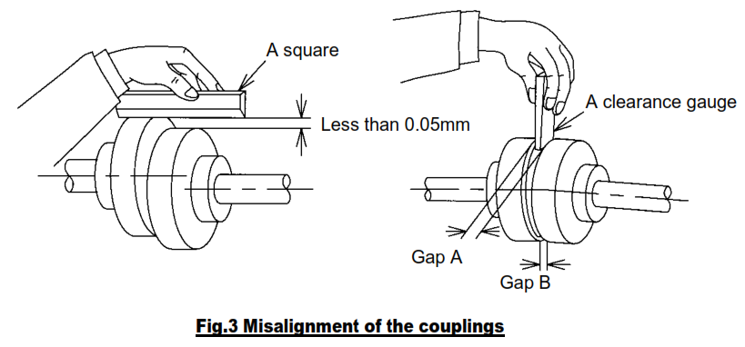
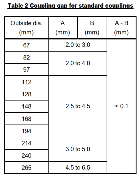
Gap A and B between coupling should be set as follow Table 2. The difference between A and B to be smaller than 0.1 mm.
4. Electrical connection
Warning
Perform wiring work correctly as specified by electrical facility technical standards and extension codes. Incorrect wiring could result in electric shock and fires.
Install and ground an earth cable. Electric shock could occur during accidents or electric leakage.
Caution
Make sure that any one of three terminals of the three-phase motor is not loose or disconnected. Running the motor with only two terminals connected could a phase interruption, burning out the motor.
The motor manual must be read and completely understood by the specialist personnel/ operators responsible prior to installation and operation of the motor
(1) All interconnecting wiring for controls and grounding should be in strict accordance with local requirements such as the USA National Electrical Code and UK IEE wiring regulations. Wiring of motor and control, overload protection and grounding should follow the instructions of connection diagrams attached to the motor.
(2) Check the following points before turning on operation switch:
(a) Installation of appropriate fuses.
(b) Correct wiring.
(c) Correct grounding.
(3) Terminal voltage in motors bearing may be within ±10 % of the rated voltage, exceeding this range will be lead to breakdown.
(4) Overloading the motor beyond the prescribed limit will reduce its efficiency, is not economical and will eventually lead to motor malfunction. We recommend that a protective motor relay be installed to prevent burnout caused by overloading.
Note
The correct direction of rotation is clockwise when looking from the motor side.
Operation
Warning
Do not operate the pump for more than 1 minute with the discharge valve closed. Doing so will increase the inner pressure of the pump, damaging the casing or plugs.
Do not touch the rotating parts such as the shaft, etc. while the pump is running. Since these parts rotate at high speed, doing so could result in injury.
Caution
If the pumped liquid is hot water, keep your hands off the pump. The pump’s surfaces will be hot, and you could get burned if you touch them.
Do not touch the motor. The motor’s surfaces will be hot, and you could get burned if you touch them.
Do not cover the motor with a blanket or cloth. Doing so could over heat the motor, setting a fire.
1. Preparation for operation
Note: After piping or Water filling, check the centering of pump again please.
(1) Do pipe flashing before operation. Without pipe flashing, there might be some abnormal wear occurring on mechanical seal or other rotating parts.
(2) Try to turn the shaft, to check that it rotates easily. If it turns stiffly or irregularly, inspect internal rusts, etc.
(3) Prime the pump. Operating the pump without priming it will cause damage. Open the suction valve, discharge valve, and air vent valve, and fill the pump to the discharge nozzle with water from the pipe line.
(4) When priming, rotate the pump manually to completely remove air from inside the impeller.
(5) Tightening nuts of Blots for gland to the Extent to which hand-cranked becomes heavy. Make sure that there is no uneven tightening happening when tightening nuts of Blots for gland. Do adjustment of gland packing according to “Adjustment of gland packing” (P.16).
Note: Do not make the water leakage value of gland packing to 0 mL/min.
2.Operation – Stopping
Warning
If there is a power failure, turn the power switch off. Otherwise, the pump may start-up suddenly when the power supply is resumed, exposing personnel to danger.
Note
The correct direction of rotation is clockwise when looking from the motor
side.
(1) Close the discharge valve and air vent valve after priming is completed. If a suction valve is equipped, open it to full turn
(2) Turn the power briefly on and off again a couple of times, and check that operation is normal. Also check the direction of rotation.
(3) Once the prescribed speed is reached, gradually open the discharge valve to start cycle operation.
(4) Check for abnormal pressure, current, vibration, or noise. Keep the cocks of the pressure gauge and compound gauge closed, except when taking measurements. These gauges may be damaged if their cocks are left open.
(5) After closing the gate valve on the discharge side, turn off the power to shut down the motor.
(6) If there is no check valve on the discharge side, when shutting down operation, gradually close the discharge valve, and then shut down the motor.
(7) Before the pump is started up for the second time and before all subsequent startups, conduct the daily inspection specified in Maintenance
Note: Run the pump at a discharge capacity that is suitable for the equipment. (Capacity that is too large or small will cause noise and vibration, and also waste power.)
3.Adjustment of gland packing・・・For gland packing type
For gland packing specification, make sure the water leakage is moderate according to Table 3. Prevent over tightening and uneven tightening gland packing from happening. If the water leakage could not be adjusted, there might be a deterioration occurring at shaft seal parts. Therefore it is necessary to exchange gland packing or both gland packing and shaft, and then adjusting the water leakage value.
(1) The tightening of gland packing
(a) Tightening nuts of Blots for gland to the Extent to which hand-cranked becomes heavy.
(b) Make sure that there is no uneven tightening happening when tightening nuts of Blots for gland.
(2) Adjustment of gland packing during operation of pump
(a) During initial operation of pump, the water leakage value is more than normal operation
(Table 3).To take 10 to 30 minutes’ running-in of pump, and making sure that you are aware of the fever, abnormal noise.
(b) During normal operation of pump, do not make the water leakage value to 0 mL/min.
(c) After running-in of pump, adjusting the water leakage value is moderate according to Table 3.
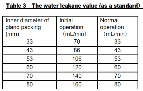
(d) Checking table of The water leakage value (as a standard).
You can also check inner diameter of gland packing from table 3.(For example, model 32-125 uses “ 33X49X8 ”gland packing, therefore inner diameter of gland packing of model 32-125 is 33 mm which is the same as the first number of gland packing’s name)
(e) When the water leakage value is huge, tightening gland packing to adjust the water leakage value to normal value. However, if you tighten gland packing in a short time, pump might be prone to fever. Therefore, you should tighten gland packing gradually at 10 to 30 minute intervals.
4.Replacement of gland packing・・・For gland packing specification
Do replacement of gland packing under the situations below.
(1) The disassembling of pump happens, such as a periodical inspection
(2) There is no more space for tightening of gland packing.
(3) The water leakage value could not be adjusted.
(4) When a significant damage or dents (0.7mm or more for one side) occurs to the shaft surface, shaft should be exchanged for new.
(5) Replace gland packing with new packing, shifting joints from 90 to 120 degrees until last joint is on the bottom.
5. Cautions for operation
Warning
If the pump is operated for long periods with the discharge valve closed, the water temperature inside the pump will rise, causing an accident. Do not operate the pump with the discharge valve closed for longer than 1 minute.
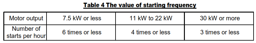
(1) The frequent starting up and stopping of the pump will cause damages. It is recommended to limit the starting up of the pump as follows:
(2) If there is a power failure, turn the power switch off. Otherwise, the pump may start-up suddenly when the power supply is resumed.
Maintenance
Warning
Disassembly and repair of the pump should only be performed by specialist maintenance technicians. Otherwise, error by personnel could result in electric shock, and the pump catching fire or operating abnormally and causing injury.
Always turn the power switch OFF before inspecting or repairing the pump. Not doing so could result in the pump starting up suddenly in auto operation, exposing personnel to danger.
Caution
If the pumped liquid is hot water, keep your hands off the pump. The pump’s surfaces will be hot, and you could get burned if you touch them.
Do not touch the motor. The motor’s surfaces will be hot, and you could get burned if you touch them.
To prevent an accident if the pump stops running or an abnormality occurs, immediately turn off the power switch.
Contact the shop from where you ordered the pump, or EBARA to perform an inspection and maintenance on the pump.
When the pump is out of use for prolonged periods such as the wintertime, water inside the pump could freeze, causing damage to the pump. Accordingly, in such situations, either drain all water from the pump or provide thermal insulation to prevent the water from freezing.
1.Daily inspection
(1) If pressure, current, capacity, vibration, or noisy differ markedly from normal, trouble of some kind is probably going to occur, and you should take prompt corrective action. Refer to Troubleshooting for diagnosis and corrective action. You are advised to post a Daily Operation Condition Check Sheet.
(2) For standard specification, allowable operating temperature of bearing is no more than Room temperature+40℃, and no more than 80℃.
(3) There should be almost no leakage if the mechanical seal is normal. If there is a large amount of leakage, replace the mechanical seal.
(4) Normally, there should be almost no leakage for a mechanical seal. However, at the beginning of operating of pump, a little water leakage from a mechanical seal is recognized. As the pump is operating for a while, the water leakage would be decremented, otherwise you should stop the pump
and check it. During daily inspection, loosing the bolts of the protector. Do not remove the bolt of the protector. It may course bolts to be lost.
(5) For gland packing specification, make sure the water leakage value is moderate according to Table 3. and preventing over tightening and uneven tightening gland packing. If the water leakage value could not be adjusted, there might be a deterioration occurring at shaft seal parts. Therefore it is necessary to exchange gland packing or both gland packing and shaft, and then adjusting the water leakage.
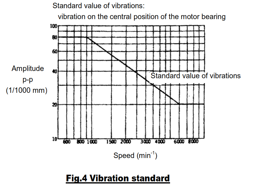
(6) Standard value of vibrations for when the pump is installed correctly and piping work has been performed correctly are shown in Fig.4. Wrong piping work can often cause excessive vibrations.
(7) Make sure that mounting bolts and terminal screws of electrical wiring are fasten firmly.
(8) Measure the insulation resistance of motor once a month. It is okay when the insulation resistance value is equal to or greater than the 5MΩ. However, when the insulation resistance value drops suddenly, no matter the insulation resistance value is more than the 5MΩ or not, the repair of motor is required
2. Prolonged stoppage and storage
(1) If you have installed a spare pump, run it from time to time and keep it ready for operation anytime.
(2) When the pump is out of use for three months or more, the gland packing unit might be rust-eaten.
Please take the old gland packing unit out, remove moisture from the stuffing box, and install new gland packing unit into the stuffing box. Also, to prevent the finished surfaces of bearing and shaft and coupling and so on being rust-eaten, doing something like painting the anti-rust oil please.
(3) When the pump is out of use for prolonged periods in the wintertime or in cold climates, the water inside the pump could freeze, causing damage to the pump. Accordingly, in such situations, provide thermal insulation to prevent the water from freezing.
(4) When the pump is out of use for three months or more, please shut off the power.
3. Replaceable parts
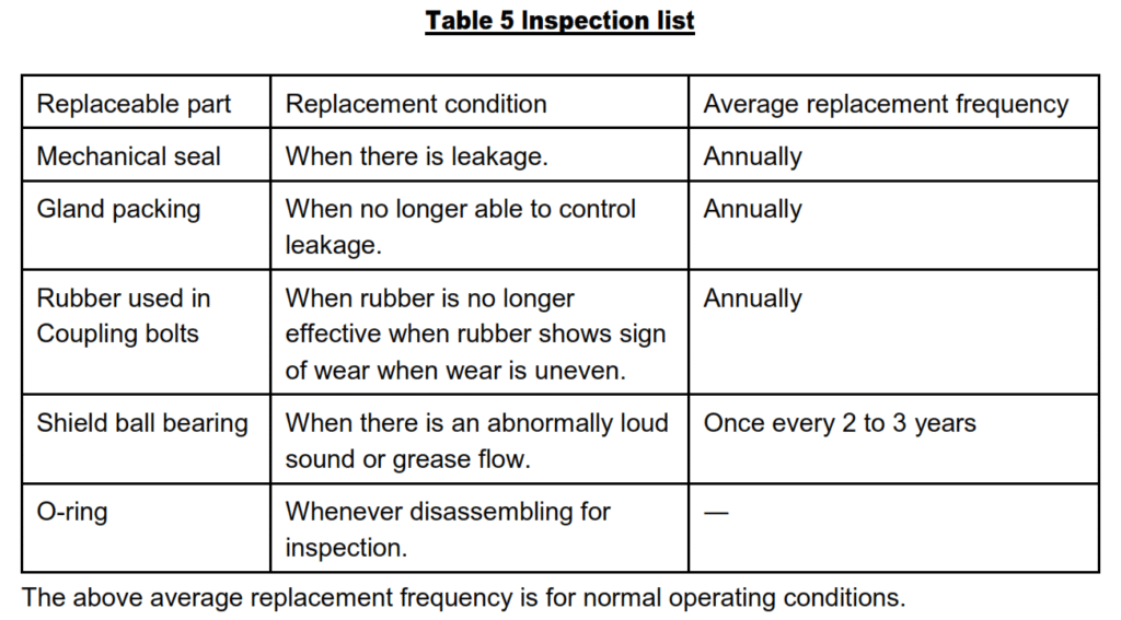
Replace the parts according to the conditions shown in Table 5.
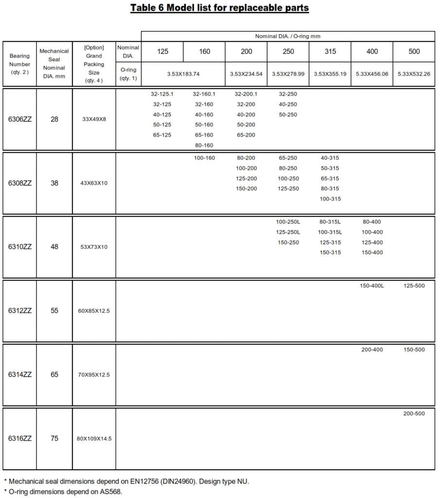
(2) The replaceable parts for each model as:
Mechanical seal, Gland packing, Shield ball bearing and O-ring.
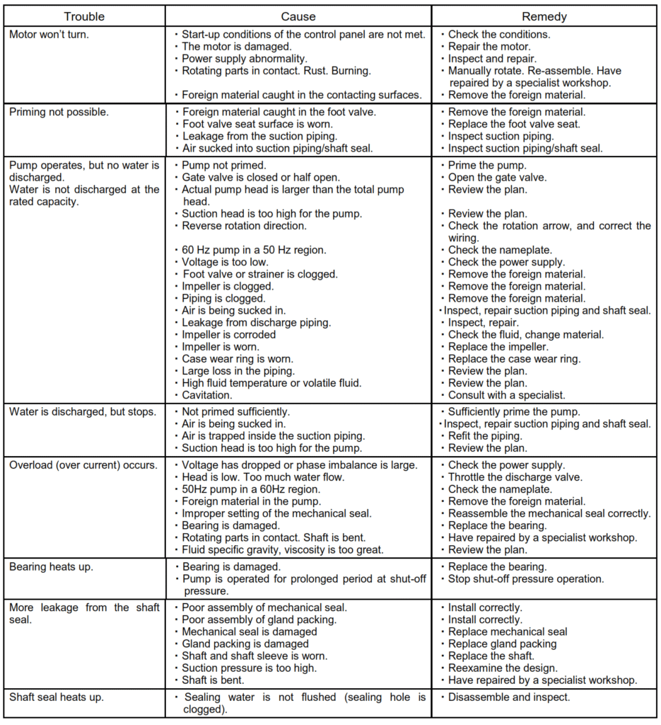
Troubleshooting
Pump
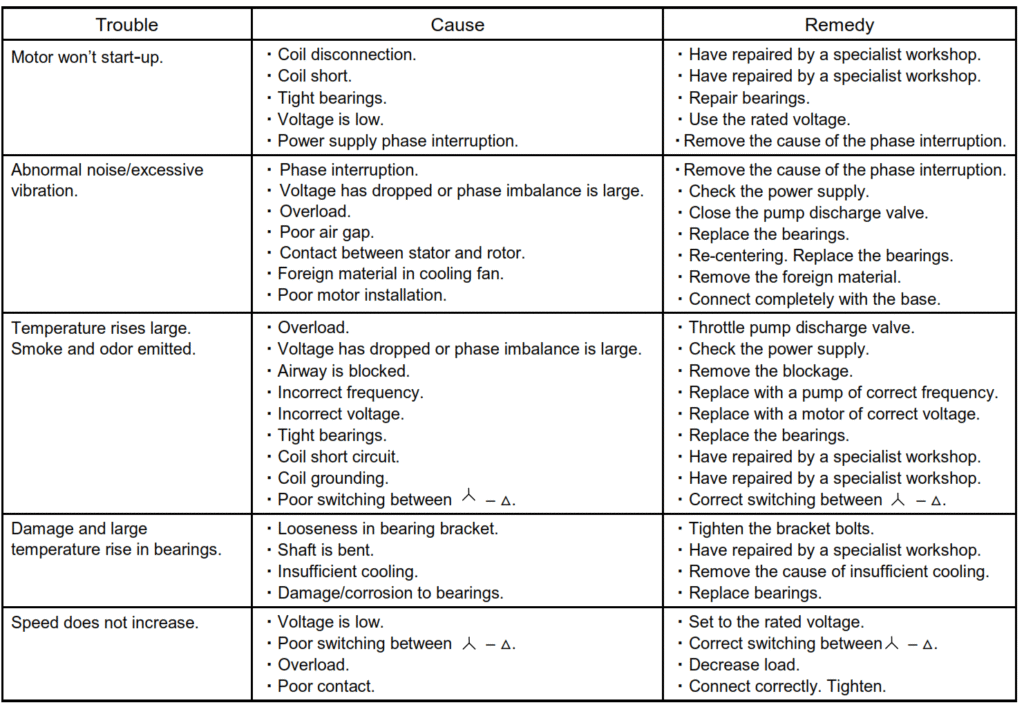
MOTOR
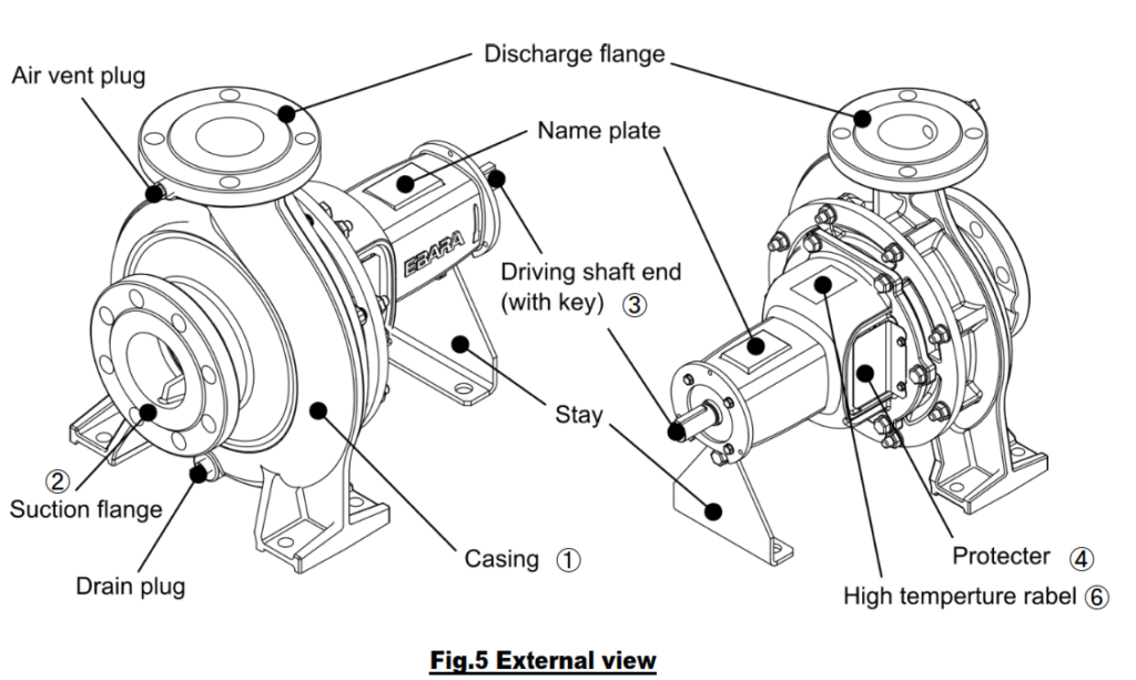
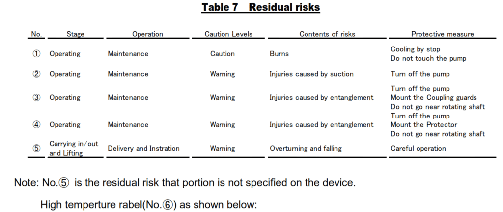
Construction
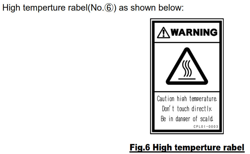
External view and residual risks
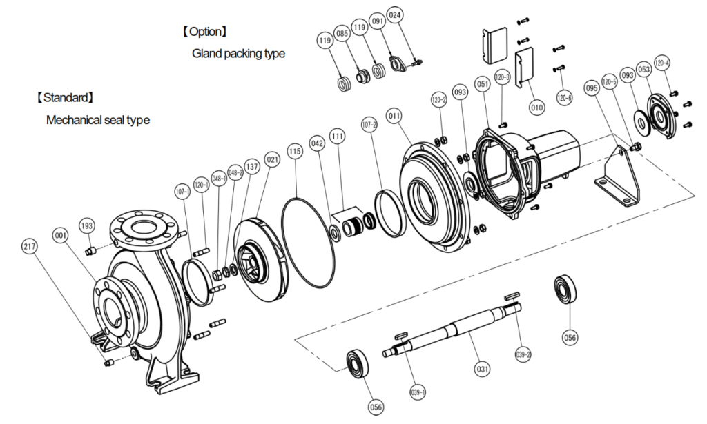
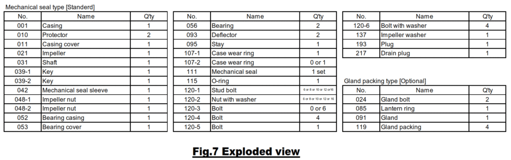
Exploded view
This figure shows a GS model for example. Depending on the model, your pump may vary slightly.
Disassembly
When disassembling pump, have a piece of cardboard or plywood ready to place the parts as you work.
Do not pile parts on top of each other. They should be laid out neatly in rows the O-ring and gasket can’t be used again once they are removed. Have replacement parts ready.
Disassemble in the following order, referring to the sectional view.
Be sure to cut off power source before beginning disassembly.
(1) Drain all water from casing.
(2) Remove the motor from the common base. Inspect shaft coupling rubber and replace if excessively worn.
(3) Remove the casing cover bolts, and remove casing cover (011) and bearing casing (052) from casing
(001). You will now be able to inspect the inside of the pump. Check for wear and other abnormal signs. Replace case wear ring (107) when wear approaches 1 mm.
(4) Remove impeller nut (048) and impeller washer (137), and remove impeller (021) from casing. if the impeller is rusted and will not come loose, tap its end lightly with a wooden hammer to release
(5) Remove the impeller key (039-1) from the main shaft (031), the casing cover from the shaft bearing frame, and the deflector from the main shaft.
(6) Mechanical seal type: at this point in disassembly, the fixed portion of the mechanical seal (111) is attached to the casing cover (011) and the rotating portion to the main shaft (031). The fixed portion of the mechanical seal can be removed by pushing it out of the shaft hole in the casing cover with a
screw driver or similar tool.
Gland packing type: remove the packing gland (091) from the casing cover (011) and take out the packing (119) and lantern ring (085). (Some models do not have a lantern ring bushing).
(7) Remove the shaft bearing cover from the shaft bearing frame and take out the main shaft. Inspect condition of the shaft bearing and replace if it does not rotate smoothly.
Note: If disassembly of the motor is necessary, consult the specialized
manufacturer.
Assembly
Assembly should be performed reverse to disassembly. Be careful of the following when assembling the pump.
(1) Mechanical seal type: wipe contacting part of mechanical seal (111) with alcohol and a dry cloth.
Gland packing type : replace gland packing with new packing, shifting joints from 90 ゚ to 120° until last joint is on the bottom.
(2) Replace the O-rings (115) with new ones.
(3) Replace all worn and/or damaged parts.
(4) Tighten the bolts and nuts gradually and in order.
Tighten torques for hexagon bolts and nuts; M6: 4.5 Nm, M8: 11 Nm, M10: 22 Nm, M12: 38 Nm, M16: 93 Nm, M20: 181 Nm, M24: 313 Nm.
※ Please obtain O-rings, shaft seals and other parts from pump dealer. The table of dimensions is given in “maintenance”.
Limited warranty
We P.T.Ebara Indonesia state that this warranty is valid for the pump set completed with driven motor.
As stipulated below, repair work is covered by this warranty. However, the scope of warranty are as follow:
(1) Unless otherwise specified in the contact the warranty period is for one (1) year after date of delivery.
(2) During the warranty period with proper pump operation, if tribune occurs due to defects in design, manufacture or material, damaged parts will be repaired/ replace free of charge based on investigation result decided by P.T.Ebara Indonesia.
(3) Repairs of the following damages and replacement of consumable parts to be used up (such as bearing, coupling rubber, packing, lubrication oil and grease, etc.) shall be subject to charge:
(a) Damages that occer due to mishandling or improper storage of the pump.
(b) Damages that occur due to fire, war, natural calamity or acts of God.
(c) Damages that occur when parts other than those stipulated by EBARA are used.
(d) Damages that occur due to miss-construction of base plate or fondation and miss-alignment of coupling done by customer/ distributor.
(e) Damages that occur due to driven motor which not supplied by P.T.Ebara Indonesia.
(f) Damages that occur due to miss-installation of electricity at driven motor.
(g) Damages that occur due to repair or reconstruction work made by any agents other than EBARA.
Leave a Reply