Installation
1.LOCATION
(1) This pump should be installed indoors. If it is to be used outdoors, some type of roof or covering will be required to protect the pump from the weather.
(2) Install where inspection and maintenance can be easily performed.
(3) Provide suitable enclosure to prevent entry of unauthorized persons.
(4) Install pump as close to water source as possible. Suction height (height from surface of liquid to center of pump) should be as low as possible, and suction piping should be short.
(5) Suction head should be less than 6 meters in certain cases, such as with hot water, suction head must be lower. To minimize suction piping loss, excessive use of elbows and valves should be avoided.
2. Piping
(1) Use adequate support for suction and discharge
piping to prevent pump and motor from becoming off center.
(2) A check valve must be installed between the pump and the discharge valve in the following cases.
When suction piping is long; when actual head is high; when pump is automatic; when water is being
pumped to pressure tank; and when two or more
pumps are in parallel operation.
(3) Install an air-release valve in piping to prevent the
unavoidable formation of air pockets due to construction. Note, however, that an air-release valve must not be installed where pressure may drop
below atmospheric pressure since the valve may
suck in air instead of expelling it.
(4) To reduce effect of water hammer install such a
device as a quick-closing check valve.
(5) Suction system:
- The end of the suction piping should be submerged to a depth of at least twice the diameter (D) of the piping, and should be at a distance between 1 to 1.5 times the diameter of the piping from the bottom of the pit.
- Install a foot valve at the end of the suction piping to block the entrance of foreign matter.
- Suction piping should be inclined upward lover 1/1001 in relation to the pump to prevent formation of air pockets.
Pipe joints must be tight so that there will be no possibility of air suction. - Keep suction piping as short and straight as possible. Do not attach a sluice valve.
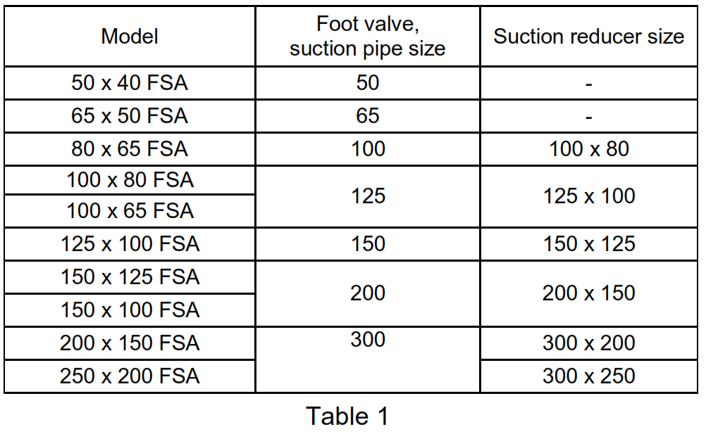
- Suction pipe sizes and suction reducer sizes should be as indicated in Table 1 . Install the suction reducer as shown in Fig. 1 to prevent the formation of air pockets. The suction reducer is available as a separate special accessory.
(6)For the influx system, we recommend that you install a cutoff valve on the suction piping to facilitate disassembly and inspection.
3. Centering
Though the pump and driver have been centered in the factory, the common bed may be distorted when the foundation bolts are inserted during installation.
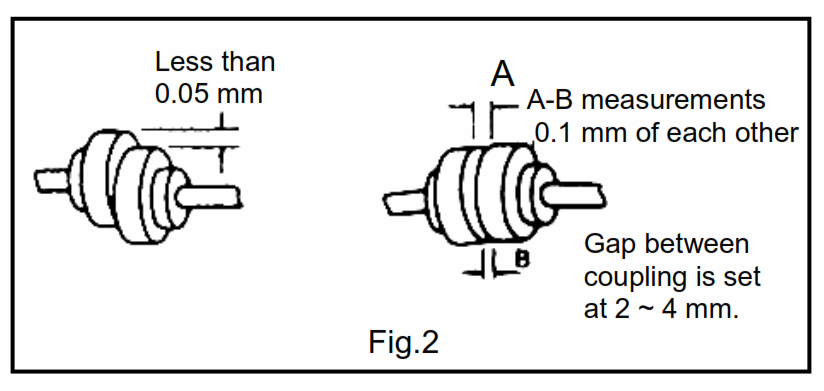
Adjust by placing tapered liners underneath the bed, and center so that the shaft coupling is within the range indicated in fig. 2.
To center a pump that has been purchased without a driver and which is to be directly driven, insert liners under the drive, and center so that the shaft coupling is within the range indicated in Fig2.
4.Electrical Wiring.
WARNING
Check that the power is locked off and disconnected before working on pump.
All electric work should be performed by a qualified electrician and all notional and local electrical codes must be observed.
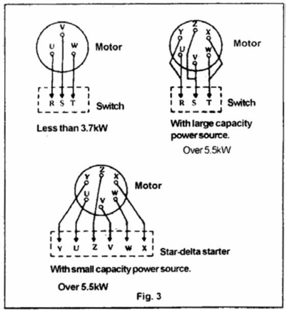
(1) Refer to Fig. 3 for correct wiring It is important that wiring be correct and that motor is properly grounded.
(2) Check the following points before turning on operation switch :
1 Is the fuse the right type ?
2 Is the wiring correct ?
3 Has motor been grounded ?
4 With a three-phase motor check for a loose or completely detached connection Operating on only two terminals will result in phase omission,
causing motor burn out.
(3) Terminal voltage in motors bearing the EBARA nameplate may be within ± 10% of the rated voltage exceeding this range will lead to breakdown
(4) Overloading the motor beyond the prescribed limit will reduce its efficiency, is not economical and will eventually lead to motor malfunction.
We recommend that a protective motor relay be installed to prevent burnout caused by overloading.
Operation
1. Before starting
To rotate by hand, remove the motor end cap and turn slot on shaft end with a screwdriver.
(1) Turn pump by hand to check for smooth rotation. If movement is sluggish or uneven, components inside the pump may be rusted or the gland packing may be too tight.
(2) Remove the coupling bolts and briefly operate the motor alone to check rotation direction. The pump should rotate in a clockwise direction when seen from the motor side. Replace coupling bolts after inspection is completed.
(3) Prime the pump. Operating the pump without prime will cause breakdown.
Open air-release valve and prime pump. If the piping is already full of water the pump can be supposed to be filled up to the discharge outlet, open the suction valve, discharge valve and air-release valve to prime.
(4) Rotate the pump by hand when priming to remove internal air from casing.
2. Operation
CAUTION
Check rotation. Correct rotation is clockwise when viewed from top of motor. Pump should be started with gate valve closed, then the operator should open the valve gradually.
(1) Close the air-release valve and discharge valve after priming has been completed. If there is a suction valve, open completely.
(2) Turn operation switch on and off two or three times to check operating condition. Attach shaft coupling guard after operation check has been completed.
(3) Begin continuous operation and gradually open discharge valve.
(4) Check that pressure, current, vibration and noise (refer to Maintenance and service) are at normal levels. Both the pressure gauge and compound gauge cocks should be kept closed except at specified times. Leaving them open may lead to malfunction.
(5) If there is no check valve on the discharge piping, close the discharge sluice valve slowly when stopping pump operation. Turn off operation switch after the sluice valve has been completely closed.
(6) Subsequent operation can proceed without checks, if all conditions are normal.
Maintenance and Service
WARNING
Disconnect power cable from power source before servicing unit. Normal maintenance should be done by qualified personnel.
Check pressure, output, voltage, current, vibration, and other specifications. Unusual readings may indicate a problem requiring immediate service. Contact your local EBARA representative as soon as possible.
Ensure that pump operation switch is off before making inspections; the pump may suddenly start if it is automatic operation type.
1. Daily inspection
(1 ) Pressure or current variations, abnormal vibration or noise are signs of malfunction.
Refer to Troubleshooting and make necessary repairs as soon as possible. We
recommend that you keep a record of daily operating conditions so that you will be able to detect early signs of trouble.
(2) The maximum allowable bearing operating temperature should not exceed 80° C.
(3) There should be no leakage if shaft sealing mechanical seal is normal. Replace entire seal if there is leakage. Gland packing leakage should be kept down to a steady drip or trickle (approx. 20 ml/min.) Do not tighten excessively or unevenly, or when pump is stopped.
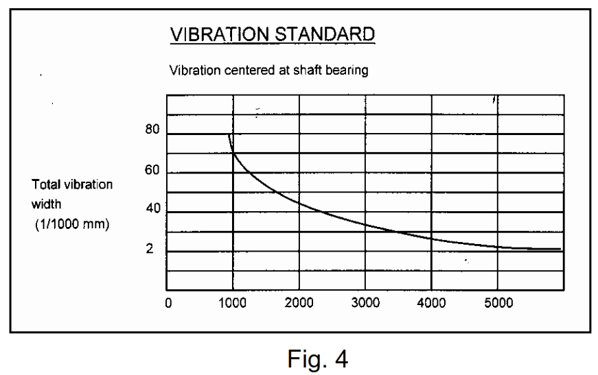
(4) Fig. 4 indicates the normal level of vibration when installation and piping are correct.
Excessive vibration may be due to conditions such as *15 (incorrect centering.) defective piping or loose foundation bolts. Inspect
carefully.
In the event that special vibration control measures are necessary, EBARA has the following available upon request: (the EBARA vibration absorber) the EBARA Flex (a flexible joint) and the EBARA pipe silencer
(pressure pulsation absorber).
2. Carefully observe the following points:
(1) Operating the pump for an extended period of time with the discharge valve closed will eventually cause pump components to be damaged.
Care should, therefore, be taken.
(2) Too frequent starting and stopping of the pump will eventually cause damage. Keep pump-starting frequency to a minimum.
(3) Be sure to turn off operation switch in event of power failure. It is dangerous to leave the switch on as the pump will suddenly start when power is restored.
3. Carefully observe the following when the pump is to be stored or remain idle for any length of time.
(1) Water remaining inside an idle pump will freeze in cold weather and cause the pump casing to burst. Be sure to insulate pump or drain water completely.
(2) Operate any auxiliary pumps occasionally to maintain best usable condition.
4. Replaceable parts
(1) Replace parts indicated in following chart as necessary.
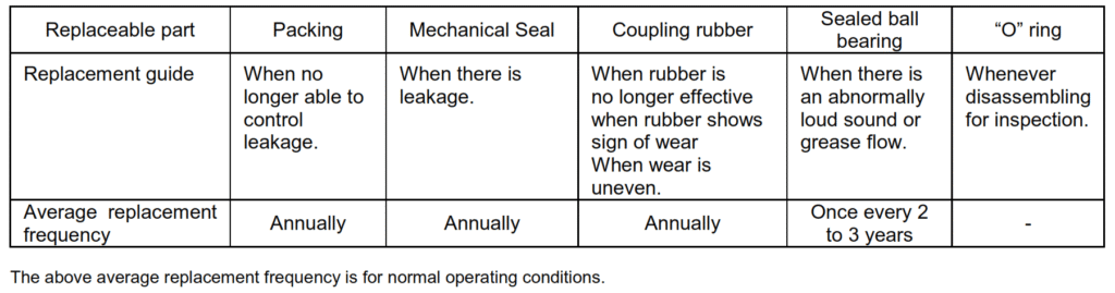
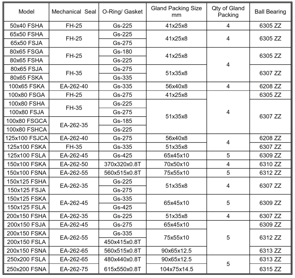
(2) The replaceable parts for this pump are as follows :
Packing, mechanical seal, and “O” ring
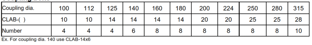
Coupling bolts
Troubleshooting
Disassembly
When disassembling pump, have a piece of cardboard or plywood ready to place the parts on as you work. Do not pile parts on top of each other. They should be laid out neatly in rows the “O” ring and gasket cannot be used again once they are removed. Have replacement parts ready.
Disassemble In the following order, referring to the sectional view.
Be sure to cut off power source before beginning disassembly.
(1) Drain all water from casing.
(2) Remove the motor from the common base.
Inspect shaft coupling rubber and replace if excessively worn.
(3) Remove the casing cover bolts, and remove casing cover and shaft bearing frame from casing. You will now be able to inspect the inside of the pump. Check for wear and other abnormal signs. Replace casing ring when
wear approaches 1 mm.
(4) Remove impeller nut (right hand thread) and impeller washer (some models do not have one), and remove impeller from casing. If the impeller is rusted and will not come loose, tap its end lightly with a wooden hammer to
release.
(5) Remove the impeller key from the main shaft (some models do not have a key), the casing cover from the shaft bearing frame, and the deflector from the main shaft.
Mechanical seal type: At this point in disassembly, the fixed portion of the
mechanical seal is attached to the casing cover and the rotating portion to the main shaft. The fixed portion of the mechanical seal can be removed by pushing it out of the shaft hole in the casing cover with a screw driver of similar tool.
Gland packing type: Remove the packing gland from the casing cover and take out the packing and lantern ring bushing (some models do not have a lantern ring bushing).
(6) Remove the shaft bearing cover from the shaft bearing frame and take out the main shaft.
Inspect condition of the shaft bearing and replace if it does not rotate smoothly.
Leave a Reply