EBARA CORPORATION
I- Our lives and pump
Water is essential for our lives. Although we usually use water without thinking, benefits that we obtain from it are immeasurable. Life with an abundance of water is our fervent hope. Pumps help us to realize this hope and therefore we cannot do without them.
It is hardly necessary to talk about the importance of pumps. If you look around, however, you will be surprised at the large number of situations which necessitate their use.

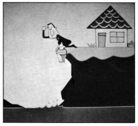
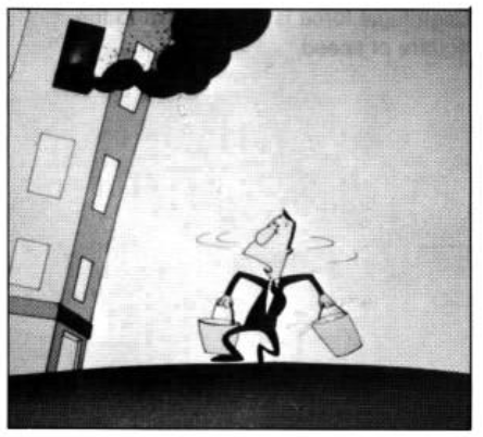
Pumps were originally developed as a means of pumping up water from low to high elevations. If we look at the history of pumps we can see the hardships undergone by men of old and the contrivances they used.
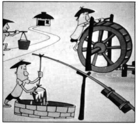
From the most primitive methods employed in early times to raise water, simple machines ap plying the laws of nature were devised and gradually pumps were evolved. When prime movers appeared on the stage, pumps developed at a rapid pace and as a result we are now able to pump up water to higher elevations than we ever thought possible,
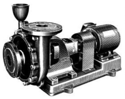
II – PRINCIPLES OF OPERATION OF THE VOLUTE PUMP
Of the various kinds of pumps which exist the volute pump is currently the most advanced. II has a large capacity and a wide range of applications. Of the various kinds of pumps which exist the volute pump is currently the most advanced. II has a large capacity and a wide range of applications.
Feature of the Volute Pump:
(1) High-speed direct coupted drive to a motor is possible. II Is compact and tow priced.
(2) II has high efficiency.
(3) The simple construction facilitates maintenance and inspection.
(4) The absence of Pulsations and low snut-olt pressure simplify piping.
(5) If can operate under a wide range of water flow rates.
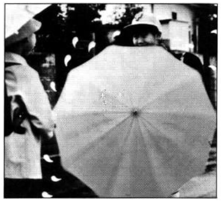
Let us take a look at how the volute pump sucks up water and discharges it. In your childhood did you ever try splashing water on an umbrella while turning it? When the umbrella is turned the water droplets are thrown out from the umbrella due to its turning motion. In the same way, when throwing a hammer, the thrower uses the powerful turning motion of his arms to hurl the hammer as far as possible
This force which tends to make objects travel a long way as a result of rotational motion is called centrifugal force. The discharge action of the volute pump is also accomplished using this same centrifugal force.
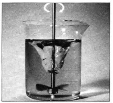
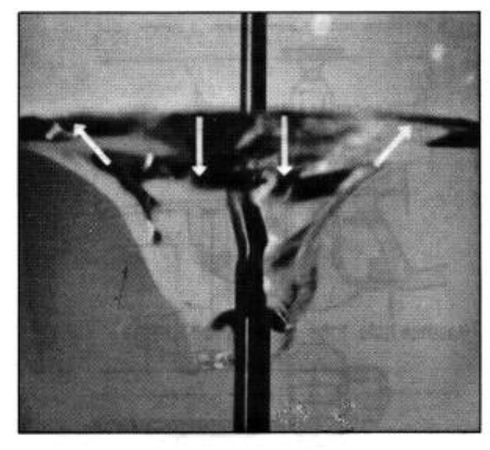
Let us try some experiments using the simple device shown on the left. When the impeller at the bottom of this device is turned, water also turns. This motion produces a depression in the water surface which is greatest at the center and least at the periphery. The reason for this is that water moves outwards under the centrifugal force resulting from the turning motion, the water pressure decreases at the center and the peripheral pressure increases.
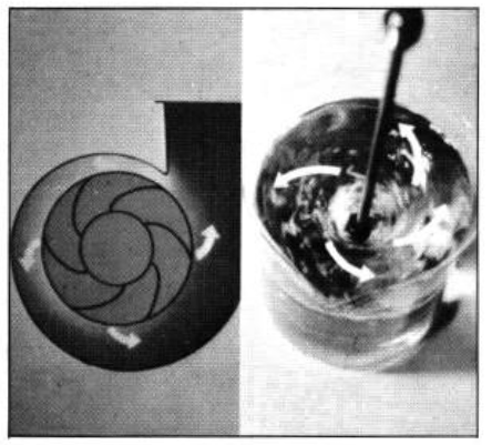
The volute pump is almost the same as this device in principle. As demonstrated in the above experiment it operates in such a manner that
when the impeller turns the internal pressure of the water is increased owing to centrifugal force and thus water is continually discharged outside.
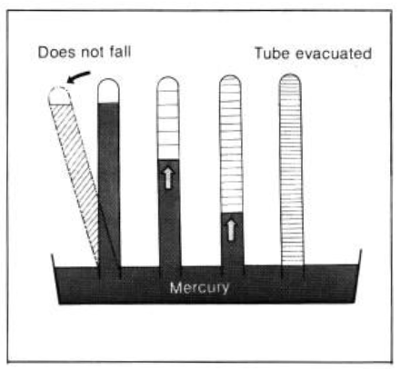
Next, let us look at how water is sucked into the pump. The picture on the left shows Torricelli’s (vacuum) experiment which is performed by deliberately creating a vacuum to prove that pressure exists in the atmosphere.
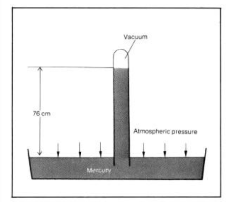
When the upper space of a glass tube of 1 m in length which is standing in a mercury bath is evacuated, mercury rises up the tube to a certain height. The level of the mercury does not fall even if the tube is tilted. This is because the mercury in the tube has been raised by the atmosphere which acts on the mercury surface of the bath, and the tube is kept at equilibrium.
When the tube inside is evacuated to an absolute vacuum, the mercury rises to a height of 76 cm. From this, can be concluded that atmospheric pressure is 76 cm Hg.
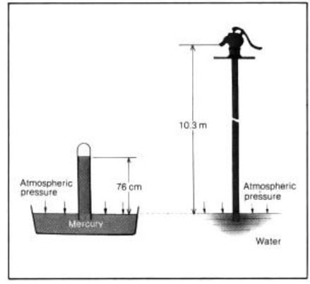
When the same experiment is applied to water, the water rises up to a height of 10.3m under atmospheric pressure owing to the fact that the specific gravity of water is lower than that of mercury.
In this way, atmospheric pressure acts on every object on the earth. We cannot normally sense this pressure on our bodies but in fact we are subject to the pressure of the atmosphere to an extent corresponding to the area of our bodies. The sucking action of the volute pump makes use of this atmospheric pressure.
Let us take another look at the experiment which was performed relative to the principle of discharge. When water is turned by the impeller, the
peripheral pressure increases and the center pressure decreases owing to centrifugal force.
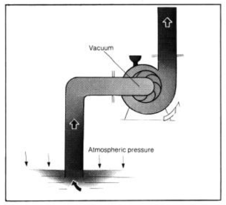
In the same way, when centrifugal force acts on the water in the pump, the center of the pump becomes a near-vacuum and water is sucked up
into the pump as a result of atmospheric pressure acting on the water surface.
In this way, the rotation of the impeller of the volute pump produces both a vacuum and a centrifugal force as a result of which suction and discharge actions take place simultaneously. The continuation of these actions permits water to be raised from a low level to a high level.
III – CONTRUCTION OF THE VOLUTE PUMP
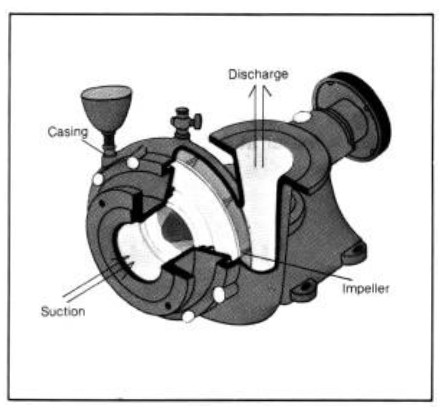
The pumping action of the volute pump is performed by four components, namely the impeller, casing, suction port and discharge
port.
(1) IMPELLER
As previously mentioned, this is the heart of the pump and serves to exert a centrifugal force upon the water contained therein.
The types of impeller which are most generally used on the volute pump include the enclosed and semi-opened types. A comparison of both types is shown in the table at below.
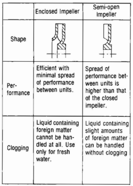
The enclosed impeller can be further subdivided into the single-liner type and double-liner type. With the double liner type a balance hole is provided to balance axial thrust (force which acts in the axial direction) exerted on the impeller while the volute pump is operating.
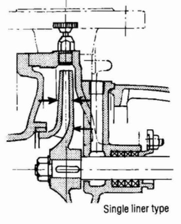
The single liner type is used with applications requiring only a small volute pump handling low pressures. This is on account of the fact that the axial thrust is low and can be adequately supported by bearings.
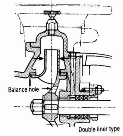
For high pressure pumps the double-liner type is used to balance the force in the casing due to the increased axial thrust which cannot be supported by bearings.
- Axial thrust, produced by the difference in pressures between the casing and the suction port, is the force which tends to push the impeller towards the suction port.
- There are other methods of balancing axial thrust such as using a balance disc seat and also, as seen in the double suction type, changing the arrangement of the impellers.
(2) CASING
This component performs the function of effectively converting the centrifugal force created by the impeller. into pressure.
Volute pumps generally employ a single volute or double-volute type casing The single volute type is used for small single-stage pumps while the double-volute type is used for multistage pumps.
In the volute pump. radial thrust (force which acts perpendicularly on the shaft) is generated as a result of flow disturbance inside the casing during pump operation.
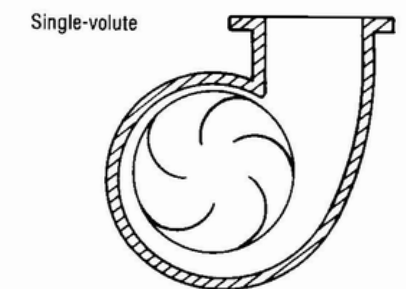
The single-volute casing is used for the single-stage pump since this radial thrust is low and can be adequately supported by bearings. For the multi-stage pump, the double-volute casing is used since the radial thrust increases in proportion to the number of impeller stages.
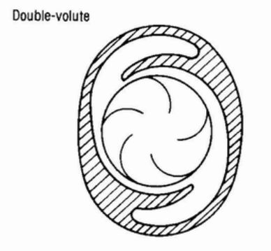
The double-volute casing is divided into two equal volutes which are arranged symmetrically at 1800 to each other so as to cancel loads which are produced in these volutes.
In addition, the following components are essential to the operation of the volute pump.
(3) Suction and discharge ports
These are used to suck in and discharge the water.
(4) Pump shaft
The pump shaft is used for transmitting the torque of the prime mover to the impeller. The shaft is designed taking into consideration the influence of forces which will act thereon. It is usually made of stainless steel or carbon steel.
(5) Bearings
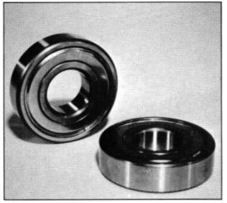
Bearings support the load of both the pump shaft and impeller together with forces which are produced during operation. Normally ball bearings are employed. Nowadays, enclosed ball bearings packed with lubrication are
often used to eliminate the necessity of oiling.
Ball bearings employed on the volute pump include both roller and slider types. Ball bearings are used as roller bearings. Slider bearings are normally made of white metal lined on a base of cast metal, steel, or bronze.
(6) Casing ring
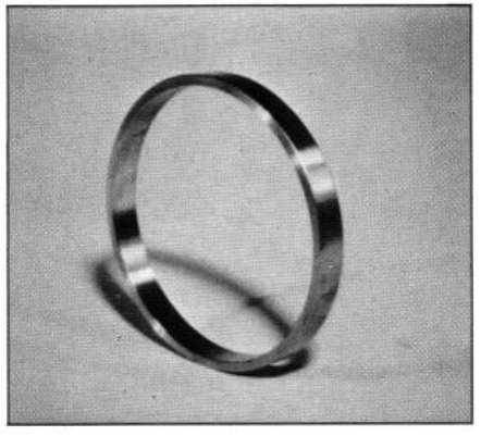
The casing ring, provided in the impeller inlet of the casing, is secured with a slight gap between it and the impeller. It is used to minimize leakage of pressurized water from the discharge side to the suction side of the pump.
(7) Gland packing
These are mounted on the section where the pump shaft passes through the casing and are used to prevent leakage of pressurized water from the casing to the outside of the pump. Generally, asbestos impregnated with oil/grease or graphite is used to adequately withstand friction generated between the
gland pieces and the pump shaft.
MECHANICAL SEALS
In addition to the gland packing, mechanical seals may also be used as seals in volute pumps. Mechanical seals are inserted so that the rotational and
stationary surfaces face and contact each other in a plane which is perpendicular to the shaft. A spring is used to ensure that the two faces do not separate as a result of vibration etc.
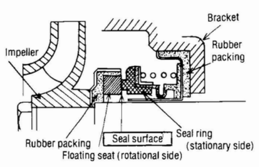
FEATURES
o Leakage can be completely prevented.
o The shaft does not wear.
o Readjustment is not required during operation.
(8) Coupling:
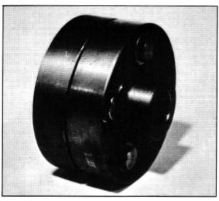
This is used to connect the pump shaft to the motor shaft. Each half is attached to the shaft ends of the pump and motor respectively so that the motor torque is transmitted, via coupling bolts, to the pump.
CLOSE COUPLED PUMP
In addition to the direct coupling method an alternative drive method is the close coupled pump in which the motor and pump are constructed in one piece. In this case the pump impeller is directly connected to the motor shaft.
FEATURES
- It is small and compact
- Vibration and/or noise due to improper centering (alignment) is eliminated
(9) Air vent valve and priming funnel
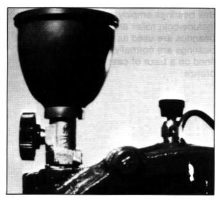
Before operating the pump, the pump and suction piping must be filled with water. This is called priming. If the impeller is turned without filling the pump with water, neither a centrifugal force nor a vacuum will be produced.
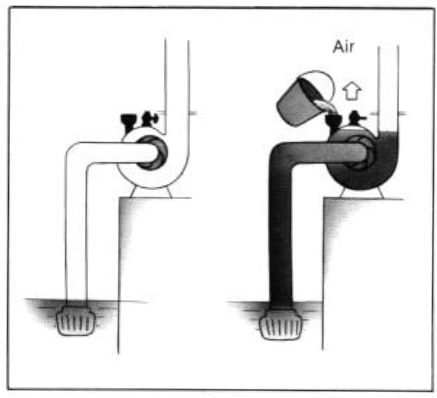
The priming operation is performed by opening the air vent valve and pouring in priming water from a funnel which forces air from the pump itself and the inlet pipe
IV-CHARACTERISTICS OF THE VOLUTE PUMP
Generally, the characteristics of the pump are given in terms of discharge capacity, head, shaft power and efficiency. We will now look at each
of these parameters in turn.
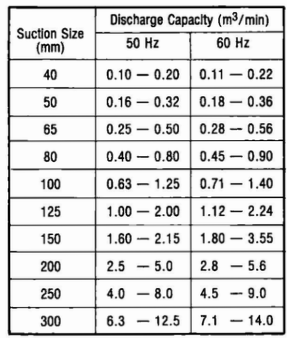
(1) Discharge capacity
This is the water volume which is discharged from the pump per unit of time. The units generally employed are m3/min or lit/min. Pump size is based on suction opening diameter.
Standard discharge flow rates together with corresponding pump suction opening diameters are given in the appropriate Japanese Industrial Standards (JIS). Extracts from relevant Japanese Industrial Standard (JIS)
(2) Head
This is the pressure which the pump produces. It is customary to represent head in terms of water (height of water column) and use the unit (m).
In the volute pump the discharge flow is inversely proportional to the head. In other words when the head is raised the discharge flow rate decreases while when the head is lowered the discharge rate increases.
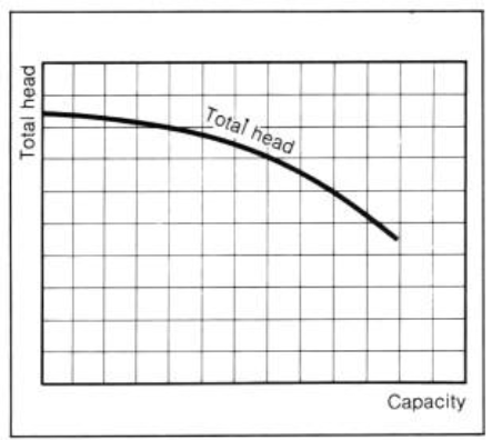
When the discharge characteristics are graphically represented using the vertical axis for the head and the horizontal axis for the discharge flow rate, the resulting curve droops as it proceeds to the right.
Relationship between head and pressure

Where
H = head (m)
P = pressure (kgf/m’)
y = specific weight of liquid (kgf/m2)
1kgf/cm3 = 10m Aq
Example: 1 kgf/cm2 = 10,000 kgf/m2
10mAq
(3) Shaft power
A prime mover is necessary to operate the pump. The power which the prime mover transmits to the pump is known as the shaft power.
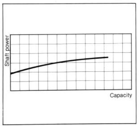
When the shaft power characteristics are graphically represented using the vertical axis for shaft power and the horizontal axis for the discharge flow rate, the curve obtained slowly rises as it proceeds to the right.
The rated output of the prime mover has sufficient margin to the actual shaft power of the pump.
Generally an electric motor is used for this purpose. The unit of output generally used is the Kilowatt (kW), however when an engine is used as the prime mover, it is represented by [PS]·
Relationship between kW and PS
1 kW = 1.360 PS
4) Efficiency
The ratio of work performed by the pump (referred to as theoretical hydraulic power) to the shaft power is known as the efficiency,
and is represented as a percentage (%).
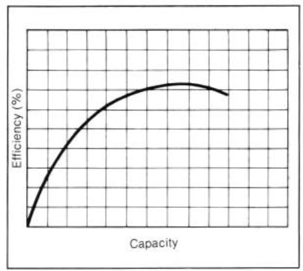
When the efficiency characteristics are graphically represented using the vertical axis for the efficiency and the horizontal axis for the discharge flow rate, the curve shown in the left hand column is obtained.
Theoretical hydraulic power
W = 0.163 yQH (kW)
w = theoretical hydraulic power (kW)
y = specific gravity of liquid
(y = 1.0 at normal water temperature)
Q = Pump capacity (m3/min)
H = head (m)
Pump efficiency
1=S
where
‘1= pump efficiency (%)
W = theoretical hydraulic power (kW)
S = shaft power (kW)
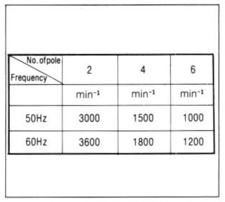
(5) Speed
Normally, an electric motor is used as the prime mover with the speed varying depend ing upon line frequency and no. of pole. The table below indicates various synchronous speeds. The actual speed of a motor however, will be lower than the synchronous speed by 3-5% on account of slip.
Characteristic curves of a pump consist of the discharge flow rate, head, shaft power and efficiency represented in one graph. It is customary to represent the curves using the horizontal axis for the discharge flow rate and the vertical axis for the head, shaft power and efficiency.
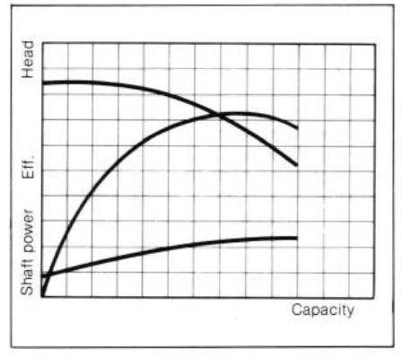
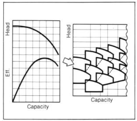
The selection chart which employed when selecting a pump is obtained only from that part of the characteristic curves corresponding to a
relatively high efficiency.
A nameplate showing Pump performance is attached thereto. The discharge flow rate, head, speed, motor output, etc. are indicated on the nameplate and guaranteed by the manufacturer.
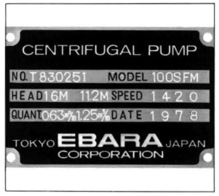
The nameplate shown on the left indicates that the pump is model SFM with an inlet diameter of 100 mm, a speed of 1420 rpm and an output of
3.7 kW. The pump provide a discharge flow rate of 0.63 m3/min at a head of 16m, or a discharge flow rate of 1.25 m3/min at a head of 11.2m.
V- PUMP PERFORMANCE VARIATION
(1) Performance variation with impeller diameter
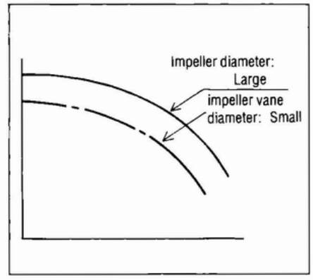
As the outside diameter of the impeller in creases, both the discharge flow rate and the head increase. The work capacity of the pump will increase and hence the shaft power will also increase.
Performance variation with impeller diameter (assuming a constant impeller width)
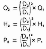
where
D1 = impeller diameter before change
D2 = impeller diameter after change
Q = discharge flow rate
H = head
P = shaft power
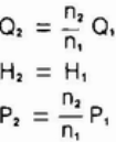
(2) Performance variation with a number of impellers
The performance of a pump varies with the number of impellers. With a multi-stage volute pump a number of impellers are arranged in series to enhance the head. With the double suction volute pump, two special type impellers are arranged in parallel to increase the discharge flow rate.
Performance variation with a number of stages of impellers
- With impellers arranged in series
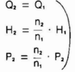
where
n.: number of impellers before change
n,: number of impellers after change
- With impellers arranged in parallel
(3) Performance variation with speed
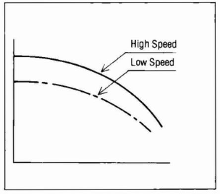
For a given pump, the performance will vary as the speed increases or decreases. Recently pumps fitted with a variable speed motor enabling the performance to be changed at will have begun to make their appearance.
Performance variation with speed
where
N1 = speed before change
N2 = speed after change
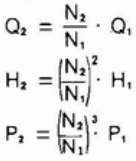
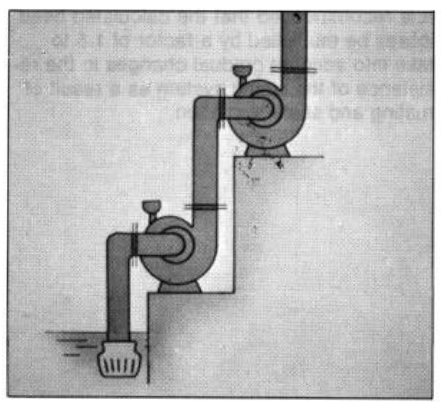
VI- HEAD AND FRICTION LOSS
In a pumping system, apart from the pump itself, the suction and discharge pipes, valves and bends etc. playa large role in delivering water
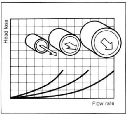
It is necessary, therefore, to take into consideration the flow friction of the pipes when looking at the pumping head. The pipe friction, which is
also known as piping friction losses, increases with the velocity of flow in the pipe
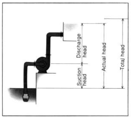
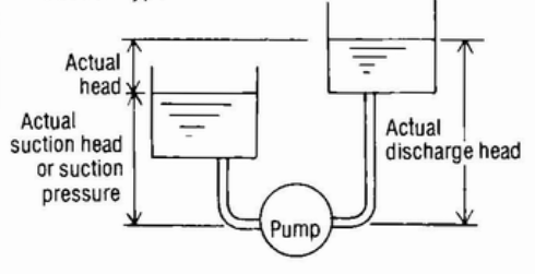
The head represented in the pump characteristics is the total head. The vertical distance from the suction water surface to the discharge surface is called the actual head, and the sum of the actual head and friction losses is the total head.
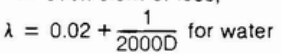
To obtain the total head, it is necessary to painstakingly calculate the head losses in detail, while the actual head can be quite easily determined. Generally, head losses are proportional to the square of the flow rate. When the characteristics are graphically represented using the vertical axis for head losses and the horizontal axis for flow rate in the previously described manner a quadratic curve is obtained which rises as it proceeds to the right. This is known as the system head curve
Since the total head is sum of the actual head and the head losses, the total head of the piping system takes the form of the curve shown in the graph at below.
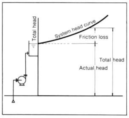
Total head = actual head + friction losses
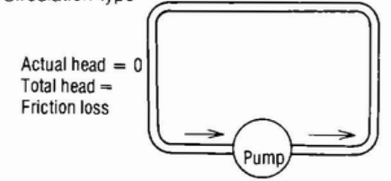
When looking at the suction performance and pressure resistance it is advisable to consider the total head. actual head and head losses classifying them into suction and discharge sides. In addition to the system shown in the diagram on the left, the following piping system is also possible.
Circulation type:
Suction type:
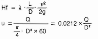
Equation to find head losses (Durcy’s formula)
where
Hf = head loss(m)
A = coefficient of loss,
L = length of piping (m)
D = inside diameter of piping (m)
v = velocity in piping (m/sec)
g = gravity acceleration (9.8 m/sec’)
Q = capacity (m3/min)
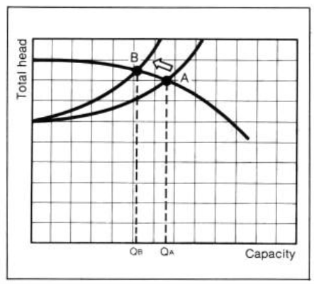
The pump is operated at the intersection be tween the head and resistance curves. This intersection is called the operating point of the pump.
When the gate valve is throttled, the resistance increases and the discharge flow rate decreases. This is a method of adjusting a discharge flow rate; in other words the flow rate is varied by shifting the operating paint of the pump.
In this case, the resistance curve varies as shown in the left hand graph and the pump is operated at the intersection between the head and resistance curves so the operating point shifts from point A to B and the discharge flow rate decreases from QA to QB. Since the resistance increases also when rust is formed and/or scale is deposited on the walls of the water feed pipes, the discharge flow rate will decrease for the same reason as when the gate valve is throttled
It is recommended that the calculated head losses be multiplied by a factor of t.5 to take into account gradual changes in the resistance of the piping system as a result of rusting and scale formation
VII- PARALLEL AND SERIES ORPERATION
In some cases pumps are operated in parallel or series in order to increase the discharge flow rate or head. This is a method whereby two or more pumps are simultaneously operated and is basically the same as the contents of section V,”PERFORMANCEVARIATIONWITH THE NUMBER OF IMPELLERS”
(1) Parallel operation
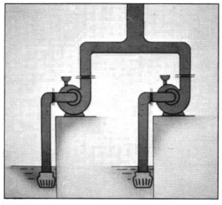
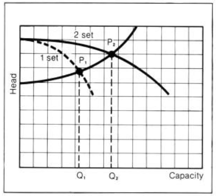
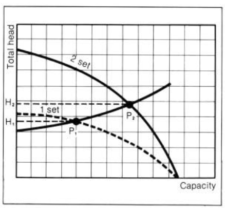
When two pumps which have the same characteristics are operated in parallel, the discharge flow rate theoretically becomes double that of a single pump for the same head point.
In actual fact, however, the discharge flowrate does not double because the pump is operated at the intersection between the parallel characteristic curve and the resistance curve. The effectiveness of parallel operation increases as the scope of the resistance curve decreases
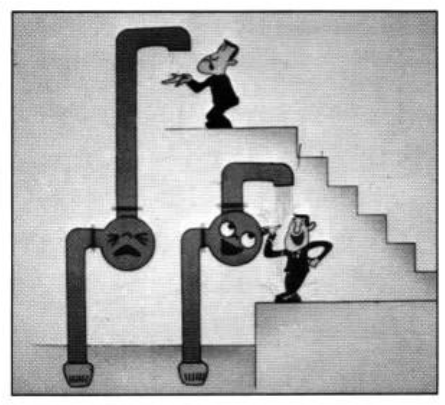
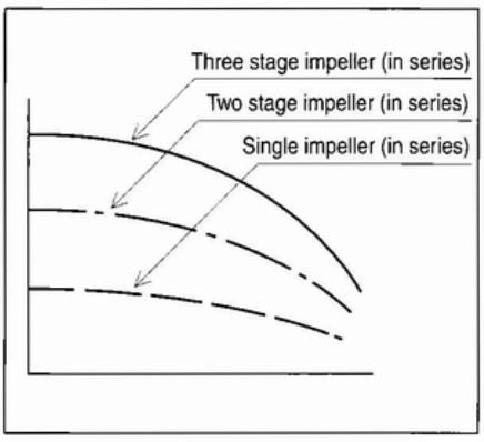
(2) Series operation
When two pumps which have the same characteristics are operated in series, the head theoretically becomes double that of a single pump for the same discharge flow rate point. In actual fact, however, the head does not double because the pump is operated at the intersection between the serial characteristic and resistance curves. Series operation be comes more effective as the resistance curve becomes steeper
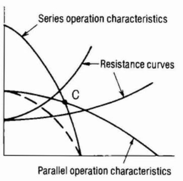
The characteristic curves of two pumps having the same characteristics when operated both in parallel and in series can be found by doubling single
pump flow rate and head applicable to operation.
When the resistance curve passes below the inter section between the parallel and serial operation characteristics, parallel operation is effective and
when it passes above the intersection, series operation is better
VIII – SUCTION PERFORMANCE
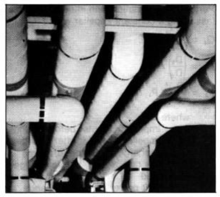
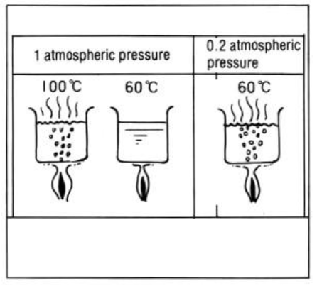
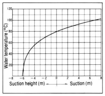
Water boils at a temperature of 100°C under normal atmospheric pressure. It is possible, how ever, to boil water at 60°C. This will occur if the
pressure is lowered to 0.2 atmospheres. If the pressure is lowered further, water will boil at an even lower temperature. Boiling means that
liquid changes to steam (vapor). The pressure existing at the boiling point is known as the saturated vapor pressure. In other words the saturated vapor pressure of water at 100°C is 1 atmosphere (10.3 mAq) and that at 60°C is 0.2 atmospheres (2 mAq)
When the pump is raising water the pressure drops the instant water enters the impeller and hence this point has the lowest pressure. When
the inlet pressure becomes lower than the saturated vapor pressure of the liquid being pumped, the liquid boils and changes to a vapor.
The vapor bubbles are fed to the pressure rise section of the impeller, and are collapsed at the point where the pressure increases, This action is accompanied by vibration and noise and results in a very large reduction in pump performance, It is known as cavitation and if it continues to occur it will eventually result in the impeller and casing being damaged.
To assure a pump does not cause cavitation, the formula below must be
used,
Av, NPSH > Req. NPSH
Av, NPSH is determined by such factors as piping, the amount of water, the temperature of liquid, etc, Av, NPSH is calculated to find how much pressure can be effectively used to operate a pump without causing cavitation,
Av, NPSH = Ha – hs – he – hv”
Conversely Req, NPSH, determined by the pump itself, denotes head required for water to enter the impeller.
Thus, if the formula Av, NPSH > Req.NPSH is accurate, cavitation will not occur,
When installing a pump where solution temperature is comparatively high or the suction head is great, study in this respect is highly recommended,
Ha= Atomosphelic pressure
hs = Suction head
he = Suction loss
hv = Saturated vapor pressure
Leave a Reply