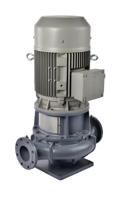
Model LPDC
1.Installation location
(1)This pump should be installed indoors. If it is to be used outdoors, some type of roof or covering will be required to protect the pump from the weather.
(2) Install where inspection and maintenance can be easily performed.
(3) Provide suitable enclosure to prevent entry of unauthorized persons.
(4) Install pump as close to water source as possible. Suction height (height
from surface of liquid to center of pump) should be as low as possible, and suction piping should be short.
(5) Suction head should be less than 6 meters in certain cases, such as with
hot water, suction head must be lower. To minimize suction piping loss, excessive use of elbows and valves should be avoided.
(6) For the influx system, we recommend that you install a cutoff valve on the suction piping to facilitate disassembly and inspection.
2.Piping
(1) Use adequate support for suction and discharge piping.
(2) A check valve must be installed between the pump and the discharge valve in the following cases.
When suction piping is long; when actual head is high; when pump is automatic; when water is being pumped to pressure tank; and when two or more pumps are in parallel operation.
(3) Install an air-release valve in piping to prevent the unavoidable formation of air pockets due to construction. Note, however, that an air-release valve must not be installed where pressure may drop below atmospheric pressure since the valve may suck in air instead of expelling it.
(4) To reduce effects of water hammer, install such a device as a quick-closing check valve.
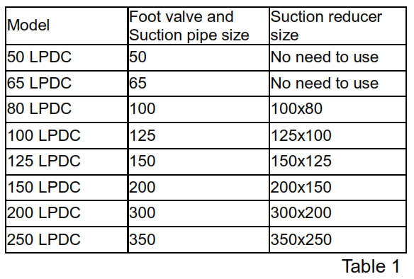
(5) Suction system:
3. Electric wiring
Please confirm that there are no loose wire connections on the motor, the primary side and secondary side of control panel, and power machine in the control panel; and remove the dust. If bad connection or dust adsorbed
on the terminal part due to loose wire connection, it may lead to heating and the danger of fire accident.
Please implement the grounding works. If it operates without firm installation of grounding wire, the danger of electric shock may appear upon fault and electric leakage.
To use and install the pump shall be implemented by specialized technician. Otherwise, it may cause fire, injury and other accidents.
Specialized technician shall correctly implement the wiring works. Please confirm whether the wiring terminals are loose. The wrong wiring works may cause fire, injury and other accidents.
Please confirm whether the connection of motor terminals is loose or dropped. In case of loose or drop connection, burn motor may be caused due to missed-phase operation.
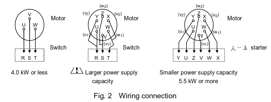
(1) Perform wiring in accordance with the instructions in Fig. 2, a connection diagram on the inner lid of the motor terminal box, or an instruction manual for the motor.
(2) Check the following before turning on a switch.
(a) An appropriate fuse is used.
(b) Wiring is correctly completed.
(c) Grounding is completed without fail.
4. Operation
- Cautions before Starting Operation
(1) Turn the pump by hand and check for smooth rotation. If pump rotation is difficult or uneven, it may be caused by internal rust etc. Locate cause and eliminate.
(3) Before starting, the pump casing must be full of liquid, manual priming may be required if the system does not automatically fill the pump casing with fluid. Open the air vent plug or valve mounted on the pump so as to exhaust air or other gas completely and confirm that pump casing is fully primed.
(4) Rotate the pump by hand when priming to exhaust internal air or other gas from pump casing.
- Start, Operation and Stop
(1) Ensure that suction valve is fully open and the discharge valve is fully closed.
(2) Turn the start switch off and on once or twice to ensure the pump is operating normally. If there are no malfunctions, the pump may be placed in continuous operation since pump shut-off operation causes rapid liquid temperature rise inside pump, with resultant damage, shut-off operation should be confined to short periods.
(3) Gradually open discharge valve and set to prescribed operation point.
(4) Check that pressure, current, vibration and noise are at normal levels. Both the pressure gauge and compound gauge cocks should be kept closed except at specified times. Leaving them open may lead to malfunction.
(5) Re-check pump and driver 30 to 60 minutes after start.
(6) During stop operation, gradually close the discharge valve before turning off the prime mover.
- Shut-down and Emergency Shut-down
(1) When the pump stops due to power failure, turn of the switch and closed discharge valve. (This prevents sudden start of pump when power is restored).
(2) Power emergency shut-down, switch off electric power and close discharge valve. - Standby Pump
For standby pump operation, fully open the suction and half open for discharge valve. Fill the pump with the liquid so that suction pressure is applied. Stop reverse pressure with check valve only and start the pump as is when restarting.
5.Maintenance
In order to maintain best operating conditions for the pump, the following maintenance and checks should be provided. Pressure gauge and compound gauge cocks should be closed except when taking readings.
This will prevent instrument damage.
(1) Supply and replacement of bearing lubricant refer to the motor manufacturer’s instruction manual for re-lubrication.
(2) Temperature on the bearing casing should not exceed room temperature plus 40°C or maximum temperature 80°C. If this temperature is exceeded, stop operation immediately and check.
(3) Do not start the pump frequently otherwise the pump may be damage.
(4) Pressure, current, vibration, noises etc. which differ greatly from normal values are a symptom of trouble. Take counter measure immediately. For this purposed, it is recommended that records be kept.
Check the following items:
Suction and discharge pressures
Current value and deviation
Bearing temperature (max. 80°C on bearing casing)
Vibration (on bearings and pump casing)
Noises
(5) Turn off the switch without fail before checking pump.
(6) Turn the pump shaft by hand once every week if the pump is stopped for long time.
(7) To prevent freeze and subsequent damage to pump during cold weather operation, drain pump or provide insulation.
(8) Replaceable part under the following condition.
Replace parts under the following conditions:
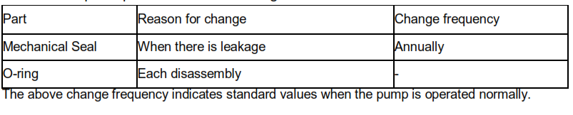
. The replaceable parts are as follows:
6.Disassembly
Prior to disassembly prepare cardboard or plywood sheet upon which to place disassembled parts on top each other, since casing O-ring cannot be re-used after disassembly, prepare replacement in advance.
Observe the following procedure for disassembly. Before disassembly,
it is necessary to turn off all power, close discharge and suction valves, (close valves in minimum flow piping) and open casing drains to completely drain pump.
Be sure cut off power source before beginning disassembly.
(1) Drain all liquid from casing
(2) Remove all bolts of casing bracket to casing and lift off the casing bracket with jack bolt and remove the casing bracket and motor by lifting the entire unit of casing bracket and motor. Inspect the inside of the pump and check for wear and other abnormal signs.
(3) Remove the impeller nut (right hand thread) and impeller washer and remove impeller from shaft. If the impeller is rusted and will not come loose, tap its end lightly with a wooden hammer to release.
(4) Remove the impeller key from the main shaft and remove mechanical seal, at this point the fixed portion of the mechanical seal is attached to the casing bracket and the rotating portion is attached to the main shaft. The fixed portion of the mechanical seal can be removed by pushing it out of the shaft hole in the casing bracket with a screw driver or similar tool.
(5) Remove all bolts of electric motor mounting from the casing and remove casing bracket.
(6) Take out the entire stub shaft from motor by losing the set screw on the stub shaft. Inspect condition of the shaft and replace there are some rubs and scratches on the shaft.
7.Assembly
Re-assemble in reverse order of disassembly.
Re-assemble of following points.
(1) Wipe contacting part of mechanical seal with a dry cloth.
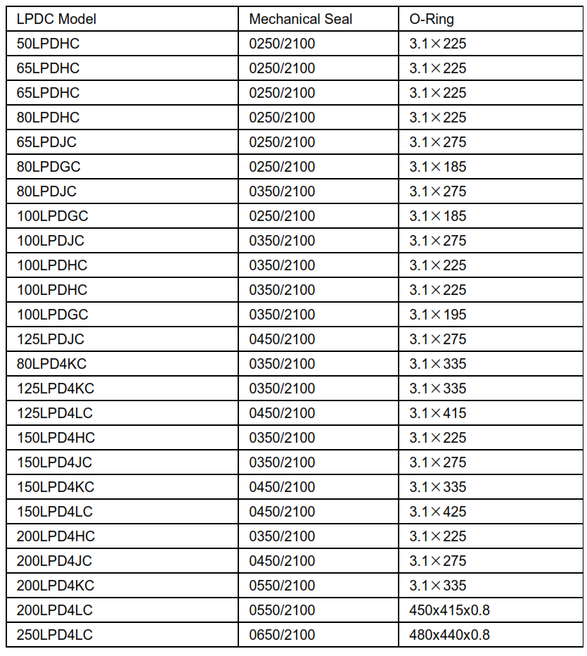
(2) Replace O-ring with a new one.
(3) Replace all parts that are excessively worn or damaged.
(4) Tighten all bolts evenly.
Please obtain O-rings and mechanical seal from pump dealer.
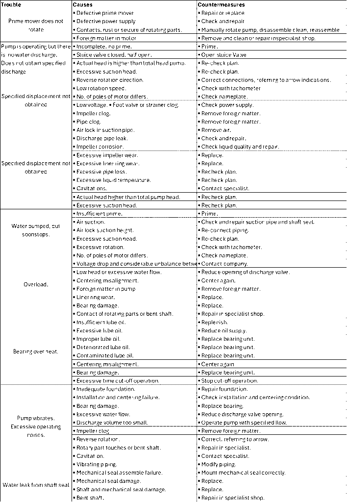
8.Troubleshooting
Leave a Reply