NEVER ALLOW THE MOTOR-DRIVEN PUMP TO OPERATE WITHOUT
WATER. DOING SO CAN SERIOUSLY DAMAGE THE INTERNAL COMPONENTS.
GENERAL WARNINGS
a) Our surface pumps are designed to operate at a temperature no higher than40°C and a level no higher than 1000 metres;
b) our motor-driven pumps cannot be used in swimming pools or similar plants;
c) prolonged motor pump operation with the delivery pipe closed can cause damage;
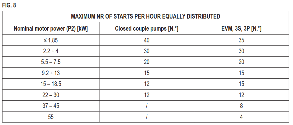
d) Avoid switching the motor pump on and off more than 50,000 times a year. If operate the pump on and off more than 50,000 times per year, the pump life may be shortened and there is a risk of premature failure. Regarding the maximum number per hour, please refer also Chapter 8;
e) during power cuts, it is advisable to disconnect the power to the pump;
f) Select the pump so that it will operate close to the best efficiency point, at
least between minimum and maximum rated flow rate.
STARTING DIAGRAM
To put the pump into operation, you must proceed as follows:
a) Insert a flat-tip screwdriver through the fan cover, in the back of the pump, until it fits into the slot made on the end of the rotor shaft;
b) Turn the screwdriver a couple of complete turns both ways;
c) Connect the pump to the system;
d) Start the pump two or three times to check system conditions;
e) restrict the delivery to cause a rapid pressure increase for a few times;
f) make sure that the noise, vibration, pressure and electrical voltage levels are normal.
STOPPING
a) Gradually interrupt water circulation in the delivery section to avoid overpressure in the piping and pump caused by water hammering;
b) Cut off the power supply.
ELECTRICAL CONNECTION
− ELECTRICAL CONNECTION MUST BE CARRIED OUT BY A QUALIFIED
ENGINEER.
− IT IS ADVISABLE TO INSTALL A HIGH INTENSITY DIFFERENTIAL
SWITCH (0.03 A) ON BOTH THE THREEPHASE AND SINGLE PHASE
VERSIONS.
MOTOR-DRIVEN SURFACE PUMPS
WHILE CONNECTING, MAKE SURE THAT BOTH THE TERMINAL BOARD
AND THE MOTOR DO NOT GET WET.
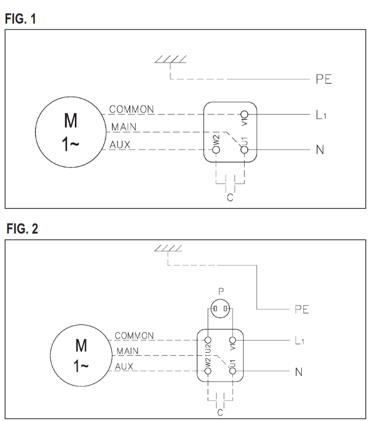
– Connection of the single phase versions must be made on the basis of
whether thermoamperometric protection “P” is internal (FIG. 1) or external
(FIG. 2).
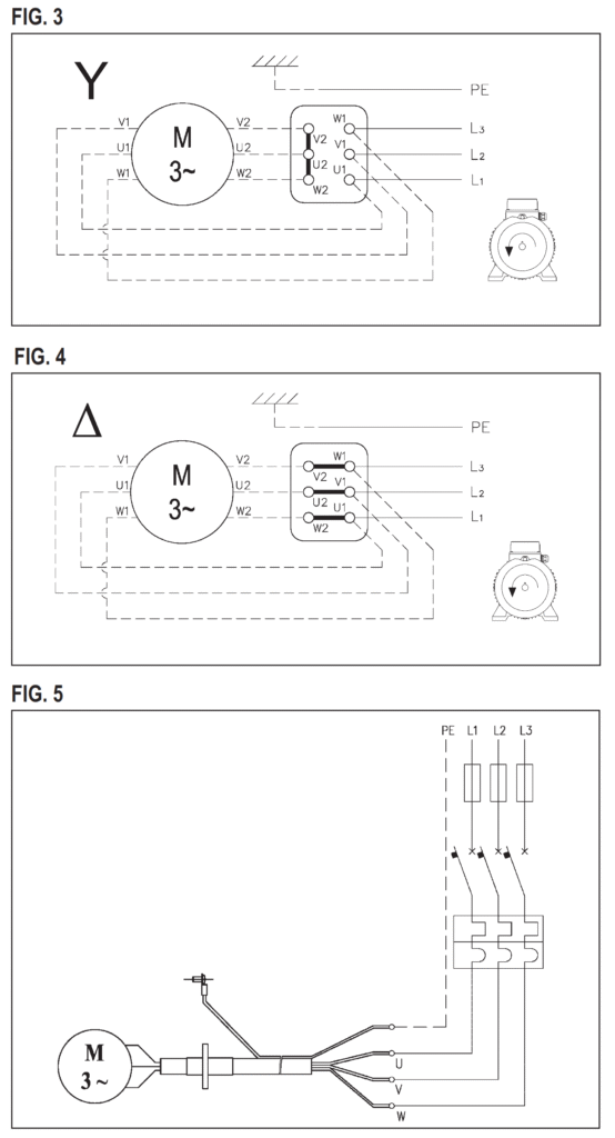
– For threephases versions, after connecting the star (FIG. 3) or triangle (FIG.4) cable to the terminal board, looking at the pump from the motor side, check that the cooling fan turns in the same way as the arrow on the label applied on the fan cover. If it is incorrect, swap two of the three wires over on the motor’s terminal strip.
For applications with inverter use a cable length <25 meters.
SUBMERSIBLE MOTOR-DRIVEN PUMPS
– In single phase versions, plug the unit into the socket.
– For threephase versions (FIG. 5), check that the motor turns in a clockwise direction looking at the pump from the top, proceed as follows: with the motor-driven pump not yet secured to the system, connect the power cable to the terminal board and switch on briefly; the pump shall start with a kick in an anti-clockwise direction, seen from the top of the pump. If the direction is wrong (clockwise), invert two of the three wires in the terminal board of the electrical panel.
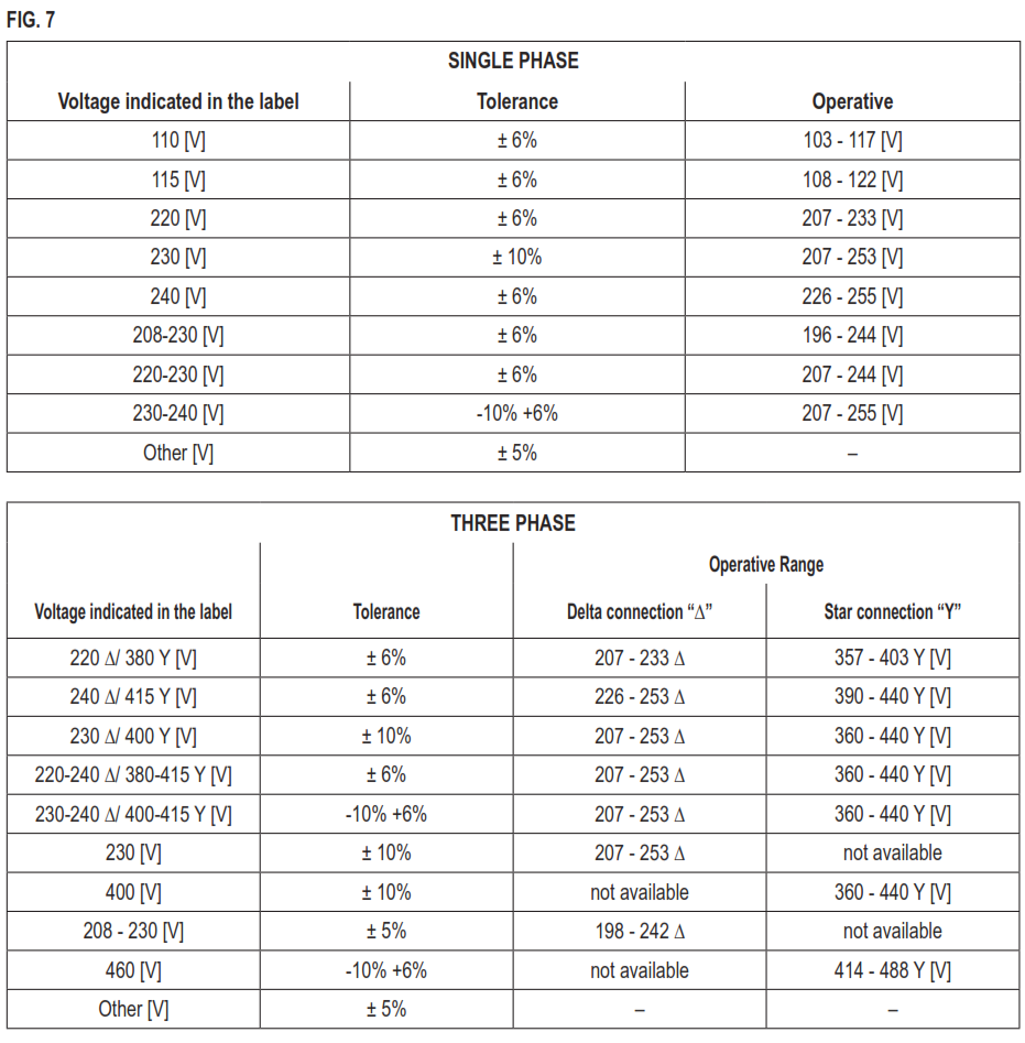
FIG. 7 shows the standard voltages shown on the plate with their respective tolerances.
DRAWING SHOWING THE ELECTRICAL CONNECTIONS OF A
SINGLE PHASE MOTOR-DRIVEN PUMP
DRAWINGS SHOWING THE ELECTRICAL CONNECTIONS OF A
THREEPHASE PUMP See FIG. 3-4-5
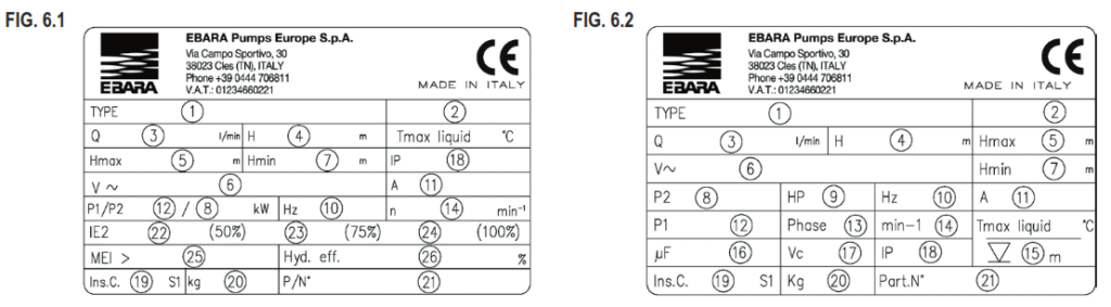
EXAMPLE OF A PLATE
See FIG. 6.1-6.2 (The manufacturer reserves the right to modify it).
MAINTENANCE AND REPAIRS
We recommend periodically checking that the pump is working correctly; pay particular attention to any abnormal noise or vibration and, for surface pumps, any mechanical seal leaks.
The main and most common special maintenance operations are generally
as follows:
− replacement of mechanical seals
− replacement of grommets
− replacement of bearings
− replacement of capacitors.
When the SURFACE pump remains inactive for a long period, it should be emptied completely, removing the discharge and filling caps, washed carefully with clean water then emptied. Do not leave water deposits inside. This operation must always be carried out whenever there is a chance of frost in order to avoid the breakdown of the pump components. If the power cord needs changing on submersible pumps, this must be done by an assistance centre only.
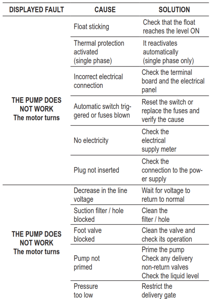
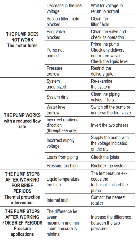
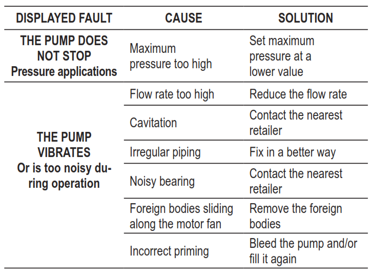
TROUBLESHOOTING
CE DECLARATION OF CONFORMITY (ORIGINAL)
We, EBARA PUMPS EURO PE S.p.A., with head office in Via Campo Sportivo, 30 38023 Cles (TN) – ITALY , hereby declare under our own responsibility that our products conform to the provisions of the following European directives: Machinery Directive 2006/42/EC; Low Voltage Directive 2014/35/EU; Electromagnetic Compatibility Directive 2014/30/EU; Directive RoHS II 2011/65/EU, Directive EcoDesign 2009/125/EC and Reg. (UE) n.547/2012, Reg. (UE) 2019/1781, Directive RAEE 2012/19/UE and the following harmonized technical standards: EN 809:1998+A1:2009; EN ISO 12100:2010, EN 60335-1:2012, IEC 60335-2-41:2012.
Leave a Reply