INSTALLATION AND OPERATING INSTRUCTIONS
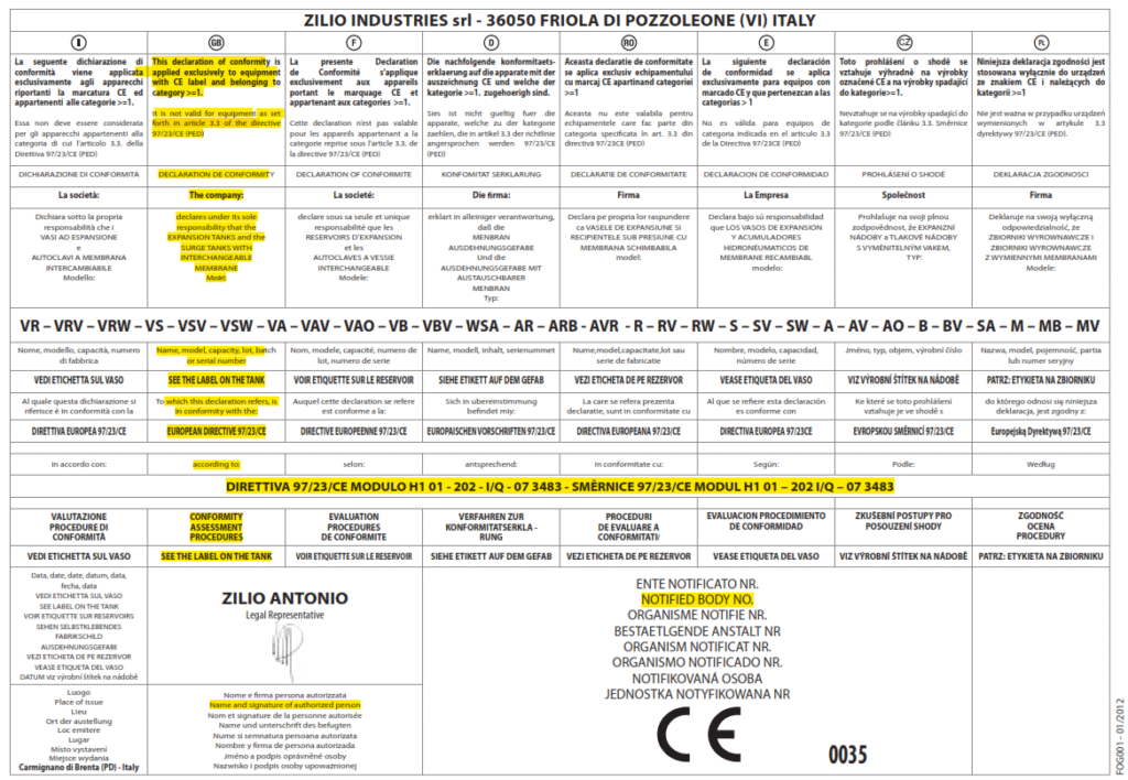
- GENERAL • This pressure / expansion tank with re-changeable membrane is manufactured by the company ZILIO INDUSTRIES srl according to the security standards of the 97/23/CE directive of the European Parliament and the Council of the European Union created on 29th May 1997 to align member state legislation on pressure equipments regulations. (Reg. 93 of
25 February 2000)
- APPLICATIONS • The pre-charge pressure of the tank allows the device to absorb the water volume fluctuation caused by the temperature increase within a closed heating circuit system or to store water under pressure in a pressurizing system. Re-changeable membrane expansion tanks are designed for heating and air-conditioning systems. Re-changeable membrane pressure tanks are designed both for the above mentioned use and also for pressurizing and sanitary warm water systems, provided the tank label states the membrane suitability.
- TECHNICAL FEATURES • The label positioned on each tank states its technical features, it is sticked with permanent glue and printed with thermo-technology and permanent ink, to preserve for long time the stated data. Each label states: date of production, tank volume in liters, temperature operating range (TS), pre charge pressure setting, maximum working pressure (PS), testing pressure (PT), fluid group 2 (air or water), class. Before installing, check that all technical features of the surge / expansion tank are compatible with the installation and that all operating limits are respected.
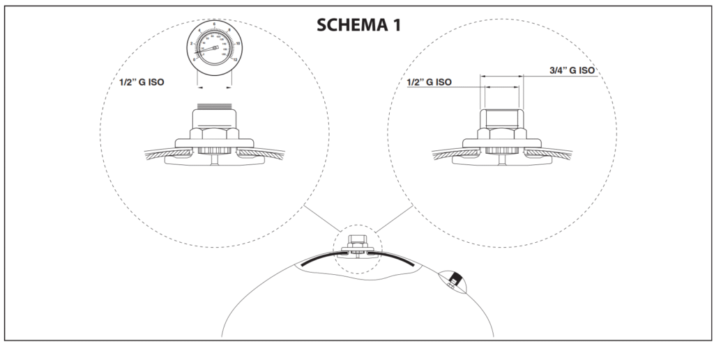
- INSTALLATION INSTRUCTIONS • Make sure to carry out an accurate cleaning of the system as the eventual presence of slags might damage the membrane. If you are removing a vessel from an existing system, make sure to turn down the electric supply on the pump control board, and divert the water supply or drain the system. Check the pre charge pressure set of the vessel on the valve, it must be 0.5 bar lower than the pressure switch setting; this device must be mounted as close as possible to the vessel. A safety valve installation is recommended to be set at the maximum working pressure of the vessel or of the system in case it is lower. As per SCHEME 1, close the hole on top of the tank with a blind cap or, as an alternative, install there a manometer to measure the pressure and/or a safety valve.
Before turning on the vessel supply, check that it is correctly installed, fill it switching on the pump until the pressure switch turns it off automatically. Turn on and off repeatedly the farest tap in order to exhaust the air bubbles inside the pipes. After this turn on one or more taps for empting the vessel; if the pump doesn’t start immediately once the tank is empty it is necessary
to increase the pressure switch settings, or to reduce the surge tank pre-charge. If the above mentioned indications have been respected, the system is ready to operate. During the system operation it is recommended to check periodically the vessel pre-charge settings, and if needed inflate and re-set the nominal pressure value.
- RECOMMENDATIONS • This product is designed for water up to 100°C (140°C for solar tanks). Do not exceed the maximum temperature and working pressure, during the installation use adequate protection systems for draining both the water and the air, in order to limit the damages caused by a water leak from the vessel. In the vessel design, external events like wind, traffic, earthquake have not been taken into account. The installer should consider those events during the installation. Install the product following the current rules. The product must be installed and periodically checked by authorized personnel only. The manufacturer doesn’t accept any responsibility for personal or material damages caused by the product if it is installed or used in incorrect way or differently from what indicated by the manufacturer.
Every six months the tank pre-charge should be checked and eventually restored at the needed value.
In order to achieve a proper operation of the tank as well as the whole system, the installation of a water-softener is recommended in case the water mean calcium carbonate content is too high.
6.REPLACEMENT OF THE MEMBRANE • On the electrical panel, turn the pump electric supply off and drain out the water from the system. Remove the vessel from the system and deflate the air using the pre charge valve. Place the tank horizontally (for the vertical models) in order to make easier the operation.
Unscrew the bolts and remove the counter flange. Unscrew the membrane holding nut on the other side of the vessel. Remove the old membrane from the tank. Position the threaded pulling device on the top of the new membrane and place the bladder inside the tank through the flange hole, making come out the threaded pulling stand from the other hole of the tank
and stick the membrane neck on the flange. Re-assemble the counter flange tightening the screws and close tight also the tie rod nut on the other side. Inflate the pre-charge chamber of the tank, and check possible air leakages from the counter flange. Install again the vessel in the system following the installation specs and check its correct operation.
Leave a Reply